- Open in CAN communication line (forward recognition camera - millimeter wave radar sensor assembly)
- Short in CAN communication line
- Open or short in forward recognition camera internal circuit
- Open or short in millimeter wave radar sensor assembly internal circuit
| Last Modified: 05-13-2024 | 6.11:8.1.0 | Doc ID: RM100000001HBMT |
| Model Year Start: 2020 | Model: GR Corolla | Prod Date Range: [01/2019 - 09/2022] |
| Title: PRE-COLLISION: PRE-COLLISION SYSTEM (for Gasoline Model): U023587; Lost Communication with Cruise Control Front Distance Range Sensor Missing Message; 2020 - 2022 MY Corolla Corolla Hatchback GR Corolla [01/2019 - 09/2022] | ||
|
DTC |
U023587 |
Lost Communication with Cruise Control Front Distance Range Sensor Missing Message |
DESCRIPTION
The forward recognition camera and millimeter wave radar sensor assembly communicate via CAN communication. If a signal is not received from the millimeter wave radar sensor assembly, the forward recognition camera stores a DTC.
|
DTC No. |
Detection Item |
DTC Detection Condition |
Trouble Area |
|---|---|---|---|
|
U023587 |
Lost Communication with Cruise Control Front Distance Range Sensor Missing Message |
3 seconds or more after the ignition switch is turned to ON, a communication malfunction with the millimeter wave radar sensor assembly is detected for 2 seconds or more. |
|
for Sedan:
|
Pattern |
DTC Location Name (Techstream Displayed Name) |
Suspected Area (Malfunction Status) |
|
|---|---|---|---|
|
Forward recognition camera (Pre-Collision System) |
Millimeter wave radar sensor assembly (Front Radar Sensor) |
||
|
U023587 |
U010487 |
||
|
○: DTC is stored
-: DTC is not stored |
|||
|
Pattern 1 |
○ |
○ |
|
|
Pattern 2 |
○ |
- |
|
HINT:
If the DTCs are output simultaneously, the inspection area can be narrowed down.
for Hatchback:
|
Pattern |
DTC Location Name (Techstream Displayed Name) |
Suspected Area (Malfunction Status) |
|
|---|---|---|---|
|
Forward recognition camera (Pre-Collision System) |
Millimeter wave radar sensor assembly (Front Radar Sensor) |
||
|
U023587 |
U010487 |
||
|
○: DTC is stored
-: DTC is not stored |
|||
|
Pattern 1 |
○ |
○ |
|
|
Pattern 2 |
○ |
- |
|
HINT:
If the DTCs are output simultaneously, the inspection area can be narrowed down.
WIRING DIAGRAM
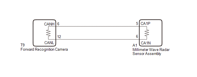
for Sedan:
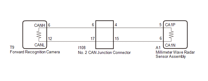
for Hatchback:
CAUTION / NOTICE / HINT
NOTICE:
-
After turning the ignition switch off, waiting time may be required before disconnecting the cable from the negative (-) battery terminal. Therefore, make sure to read the disconnecting the cable from the negative (-) battery terminal notices before proceeding with work.
Click here
![2020 MY Corolla Corolla Hatchback Corolla HV GR Corolla [01/2019 - 03/2019]; INTRODUCTION: REPAIR INSTRUCTION: INITIALIZATION](/t3Portal/stylegraphics/info.gif)
- When replacing the millimeter wave radar sensor assembly, always replace it with a new one. If a millimeter wave radar sensor assembly which was installed to another vehicle is used, the information stored in the millimeter wave radar sensor assembly will not match the information from the vehicle and a DTC may be stored.
-
When the millimeter wave radar sensor assembly has been replaced with a new one, it is necessary to perform millimeter wave radar sensor assembly adjustment and front radar acceleration sensor calibration, and to clear the vehicle control history.
Click here
- When replacing the forward recognition camera, always replace it with a new one. If a forward recognition camera which was installed to another vehicle is used, the information stored in the forward recognition camera will not match the information from the vehicle and a DTC may be stored.
-
When the forward recognition camera has been replaced with a new one or the windshield glass has been removed and installed, it is necessary to perform forward recognition camera adjustment and to clear the vehicle control history.
HINT:
Forward recognition camera adjustment can be performed by using either One Time Recognition or Sequential Recognition. When clearing vehicle control history, refer to the following links:
One Time Recognition: Click here
Sequential Recognition: Click here
PROCEDURE
|
1. |
CHECK VEHICLE TYPE |
(a) Check vehicle type.
|
Result |
Proceed to |
|---|---|
|
for Sedan |
A |
|
for Hatchback |
B |
| B |

|
|

|
2. |
CHECK FOR DTCs |
(a) Using the Techstream, check for front radar sensor system DTCs.
Body Electrical > Front Radar Sensor > Trouble Codes
|
Result |
Proceed to |
|---|---|
|
DTC U010487 is output |
A |
|
DTC U010487 is not output |
B |
| B |
|
|
|
3. |
CHECK CAN BUS LINES |
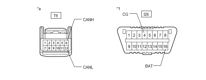
(a) Disconnect the T9 forward recognition camera connector.
|
*1 |
DLC3 |
- |
- |
|
*a |
Front view of wire harness connector (to Forward Recognition Camera) |
- |
- |
(b) Measure the resistance according to the value(s) in the table below.
Standard Resistance:
|
Tester Connection |
Condition |
Specified Condition |
|---|---|---|
|
T9-6 (CANH) - T9-12 (CANL) |
Cable disconnected from negative (-) battery terminal |
108 to 132Ω |
(c) Measure the resistance according to the value(s) in the table below.
Standard Resistance:
|
Tester Connection |
Condition |
Specified Condition |
|---|---|---|
|
T9-6 (CANH) - I26-4 (CG) |
Cable disconnected from negative (-) battery terminal |
200 Ω or higher |
|
T9-12 (CANL) - I26-4 (CG) |
Cable disconnected from negative (-) battery terminal |
200 Ω or higher |
|
T9-6 (CANH) - I26-16 (BAT) |
Cable disconnected from negative (-) battery terminal |
6 kΩ or higher |
|
T9-12 (CANL) - I26-16 (BAT) |
Cable disconnected from negative (-) battery terminal |
6 kΩ or higher |
(d) Connect the T9 forward recognition camera connector.
| OK |
|
|
|
4. |
CHECK CAN BUS LINES |
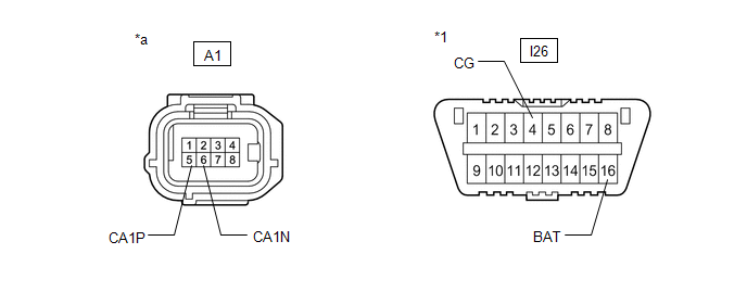
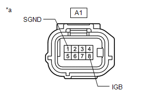
(a) Disconnect the A1 millimeter wave radar sensor assembly connector.
|
*1 |
DLC3 |
- |
- |
|
*a |
Front view of wire harness connector (to Millimeter Wave Radar Sensor Assembly) |
- |
- |
(b) Measure the resistance according to the value(s) in the table below.
Standard Resistance:
|
Tester Connection |
Condition |
Specified Condition |
|---|---|---|
|
A1-5 (CA1P) - A1-6 (CA1N) |
Cable disconnected from negative (-) battery terminal |
108 to 132Ω |
(c) Measure the resistance according to the value(s) in the table below.
Standard Resistance:
|
Tester Connection |
Condition |
Specified Condition |
|---|---|---|
|
A1-5 (CA1P) - I26-4 (CG) |
Cable disconnected from negative (-) battery terminal |
200 Ω or higher |
|
A1-6 (CA1N) - I26-4 (CG) |
Cable disconnected from negative (-) battery terminal |
200 Ω or higher |
|
A1-5 (CA1P) - I26-16 (BAT) |
Cable disconnected from negative (-) battery terminal |
6 kΩ or higher |
|
A1-6 (CA1N) - I26-16 (BAT) |
Cable disconnected from negative (-) battery terminal |
6 kΩ or higher |
(d) Connect the A1 millimeter wave radar sensor assembly connector.
| OK |
|
| NG |
|
REPAIR OR REPLACE HARNESS OR CONNECTOR |
|
5. |
CHECK CONNECTOR (MILLIMETER WAVE RADAR SENSOR ASSEMBLY) |
(a) Check the locking part and terminals of the millimeter wave radar sensor assembly connector.
NOTICE:
- Make sure the connector is not loose or disconnected.
- Make sure that the connector and terminals are not deformed or damaged.
OK:
The connector and terminals are normal.
| NG |
|
REPAIR OR REPLACE HARNESS OR CONNECTOR (MILLIMETER WAVE RADAR SENSOR ASSEMBLY) |
|
|
6. |
CHECK HARNESS AND CONNECTOR (POWER SOURCE CIRCUIT) |
(a) Disconnect the cable from the negative (-) battery terminal.
|
(b) Disconnect the A1 millimeter wave radar sensor assembly connector. |
|
(c) Measure the resistance according to the value(s) in the table below.
Standard Resistance:
|
Tester Connection |
Condition |
Specified Condition |
|---|---|---|
|
A1-1 (SGND) - Body ground |
Always |
Below 1 Ω |
(d) Connect the cable to the negative (-) battery terminal.
(e) Measure the voltage according to the value(s) in the table below.
Standard Voltage:
|
Tester Connection |
Condition |
Specified Condition |
|---|---|---|
|
A1-8 (IGB) - Body ground |
Ignition switch ON |
11 to 14 V |
(f) Connect the A1 millimeter wave radar sensor assembly connector.
| NG |
|
REPAIR OR REPLACE HARNESS OR CONNECTOR (MILLIMETER WAVE RADAR SENSOR ASSEMBLY POWER SOURCE CIRCUIT) |
|
|
7. |
INSPECT MILLIMETER WAVE RADAR SENSOR ASSEMBLY (WAVEFORM) |
(a) Turn the ignition switch off.
(b) Disconnect the T9 forward recognition camera connector.
(c) Turn the ignition switch to ON.
(d) Using an oscilloscope, measure the waveform at T9 forward recognition camera connector.
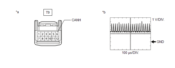
|
*a |
Front view of wire harness connector (to Forward Recognition Camera Connector) |
*b |
Waveform |
Measurement Condition:
|
Tester Connection |
Condition |
Tool Setting |
|---|---|---|
|
T9-6 (CANH) - Body ground |
Ignition switch ON |
1 V/DIV., 100 μs/DIV. |
NOTICE:
The oscilloscope waveform is for reference only and does not include noise, fluctuations, etc.
OK:
A waveform similar to that in the illustration can be observed.
(e) Connect the T9 forward recognition camera connector.
| OK |
|
| NG |
|
|
8. |
CHECK FOR DTCs |
(a) Using the Techstream, check for front radar sensor system DTCs.
Body Electrical > Front Radar Sensor > Trouble Codes
|
Result |
Proceed to |
|---|---|
|
DTC U010487 is output |
A |
|
DTC U010487 is not output |
B |
| B |
|
|
|
9. |
CHECK CAN BUS LINES (NO. 2 CAN JUNCTION CONNECTOR) |
(a) Disconnect the cable from the negative (-) battery terminal.
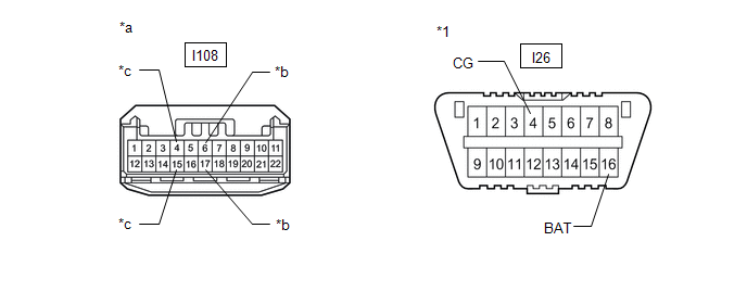
(b) Disconnect the I108 No. 2 CAN junction connector.
|
*1 |
DLC3 |
- |
- |
|
*a |
Front view of wire harness connector (to No. 2 CAN Junction Connector) |
*b |
to Forward Recognition Camera |
|
*c |
to Millimeter Wave Radar Sensor Assembly |
- |
- |
(c) Measure the resistance according to the value(s) in the table below.
Standard Resistance:
|
Tester Connection |
Condition |
Specified Condition |
Connected to |
|---|---|---|---|
|
I108-6 - I108-17 |
Cable disconnected from negative (-) battery terminal |
108 to 132 Ω |
Forward Recognition Camera |
|
I108-4 - I108-15 |
Cable disconnected from negative (-) battery terminal |
108 to 132 Ω |
Millimeter Wave Radar Sensor Assembly |
(d) Measure the resistance according to the value(s) in the table below.
Standard Resistance:
|
Tester Connection |
Condition |
Specified Condition |
Connected to |
|---|---|---|---|
|
I108-6 - I26-4(CG) |
Cable disconnected from negative (-) battery terminal |
200 Ω or higher |
Forward Recognition Camera |
|
I108-17 - I26-4(CG) |
Cable disconnected from negative (-) battery terminal |
200 Ω or higher |
|
|
I108-6 - I26-16(BAT) |
Cable disconnected from negative (-) battery terminal |
6 kΩ or higher |
|
|
I108-17 - I26-16(BAT) |
Cable disconnected from negative (-) battery terminal |
6 kΩ or higher |
|
|
I108-4 - I26-4(CG) |
Cable disconnected from negative (-) battery terminal |
200 Ω or higher |
Millimeter Wave Radar Sensor Assembly |
|
I108-15 - I26-4(CG) |
Cable disconnected from negative (-) battery terminal |
200 Ω or higher |
|
|
I108-4 - I26-16(BAT) |
Cable disconnected from negative (-) battery terminal |
6 kΩ or higher |
|
|
I108-15 - I26-16(BAT) |
Cable disconnected from negative (-) battery terminal |
6 kΩ or higher |
(e) Connect the I108 No. 2 CAN junction connector.
|
Result |
Proceed to |
|---|---|
|
OK |
A |
|
NG (Connected to: Forward Recognition Camera) |
B |
|
NG (Connected to: Millimeter Wave Radar Sensor Assembly) |
C |
| A |
|
REPLACE NO. 2 CAN JUNCTION CONNECTOR |
| C |
|
|
|
10. |
CHECK CAN BUS LINES (FORWARD RECOGNITION CAMERA - NO. 2 CAN JUNCTION CONNECTOR) |
(a) Disconnect the T9 forward recognition camera connector.
|
*1 |
DLC3 |
- |
- |
|
*a |
Front view of wire harness connector (to Forward Recognition Camera) |
- |
- |
(b) Measure the resistance according to the value(s) in the table below.
Standard Resistance:
|
Tester Connection |
Condition |
Specified Condition |
|---|---|---|
|
T9-6 (CANH) - T9-12 (CANL) |
Cable disconnected from negative (-) battery terminal |
108 to 132Ω |
(c) Measure the resistance according to the value(s) in the table below.
Standard Resistance:
|
Tester Connection |
Condition |
Specified Condition |
|---|---|---|
|
T9-6 (CANH) - I26-4 (CG) |
Cable disconnected from negative (-) battery terminal |
200 Ω or higher |
|
T9-12 (CANL) - I26-4 (CG) |
Cable disconnected from negative (-) battery terminal |
200 Ω or higher |
|
T9-6 (CANH) - I26-16 (BAT) |
Cable disconnected from negative (-) battery terminal |
6 kΩ or higher |
|
T9-12 (CANL) - I26-16 (BAT) |
Cable disconnected from negative (-) battery terminal |
6 kΩ or higher |
(d) Connect the T9 forward recognition camera connector.
| OK |
|
| NG |
|
REPAIR OR REPLACE CAN BUS MAIN LINE OR CONNECTOR (FORWARD RECOGNITION CAMERA - NO. 2 CAN JUNCTION CONNECTOR) |
|
11. |
CHECK CAN BUS LINES (MILLIMETER WAVE RADAR SENSOR ASSEMBLY - NO. 2 CAN JUNCTION CONNECTOR) |
(a) Disconnect the A1 millimeter wave radar sensor assembly connector.
|
*1 |
DLC3 |
- |
- |
|
*a |
Front view of wire harness connector (to Millimeter Wave Radar Sensor Assembly) |
- |
- |
(b) Measure the resistance according to the value(s) in the table below.
Standard Resistance:
|
Tester Connection |
Condition |
Specified Condition |
|---|---|---|
|
A1-5 (CA1P) - A1-6 (CA1N) |
Cable disconnected from negative (-) battery terminal |
108 to 132Ω |
(c) Measure the resistance according to the value(s) in the table below.
Standard Resistance:
|
Tester Connection |
Condition |
Specified Condition |
|---|---|---|
|
A1-5 (CA1P) - I26-4 (CG) |
Cable disconnected from negative (-) battery terminal |
200 Ω or higher |
|
A1-6 (CA1N) - I26-4 (CG) |
Cable disconnected from negative (-) battery terminal |
200 Ω or higher |
|
A1-5 (CA1P) - I26-16 (BAT) |
Cable disconnected from negative (-) battery terminal |
6 kΩ or higher |
|
A1-6 (CA1N) - I26-16 (BAT) |
Cable disconnected from negative (-) battery terminal |
6 kΩ or higher |
(d) Connect the A1 millimeter wave radar sensor assembly connector.
| OK |
|
| NG |
|
REPAIR OR REPLACE CAN BUS MAIN LINE OR CONNECTOR (MILLIMETER WAVE RADAR SENSOR ASSEMBLY - NO. 2 CAN JUNCTION CONNECTOR) |
|
12. |
CHECK CONNECTOR (MILLIMETER WAVE RADAR SENSOR ASSEMBLY) |
(a) Check the locking part and terminals of the millimeter wave radar sensor assembly connector.
NOTICE:
- Make sure the connector is not loose or disconnected.
- Make sure that the connector and terminals are not deformed or damaged.
OK:
The connector and terminals are normal.
| NG |
|
REPAIR OR REPLACE HARNESS OR CONNECTOR (MILLIMETER WAVE RADAR SENSOR ASSEMBLY) |
|
|
13. |
CHECK HARNESS AND CONNECTOR (POWER SOURCE CIRCUIT) |
(a) Disconnect the cable from the negative (-) battery terminal.
|
(b) Disconnect the A1 millimeter wave radar sensor assembly connector. |
|
(c) Measure the resistance according to the value(s) in the table below.
Standard Resistance:
|
Tester Connection |
Condition |
Specified Condition |
|---|---|---|
|
A1-1 (SGND) - Body ground |
Always |
Below 1 Ω |
(d) Connect the cable to the negative (-) battery terminal.
(e) Measure the voltage according to the value(s) in the table below.
Standard Voltage:
|
Tester Connection |
Condition |
Specified Condition |
|---|---|---|
|
A1-8 (IGB) - Body ground |
Ignition switch ON |
11 to 14 V |
(f) Connect the A1 millimeter wave radar sensor assembly connector.
| NG |
|
REPAIR OR REPLACE HARNESS OR CONNECTOR (MILLIMETER WAVE RADAR SENSOR ASSEMBLY POWER SOURCE CIRCUIT) |
|
|
14. |
INSPECT MILLIMETER WAVE RADAR SENSOR ASSEMBLY (WAVEFORM) |
(a) Turn the ignition switch off.
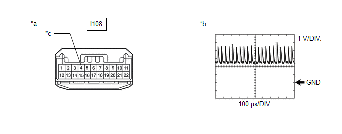
(b) Disconnect the I108 No. 2 CAN junction connector.
(c) Turn the ignition switch to ON.
(d) Using an oscilloscope, measure the waveform at I108 No. 2 CAN junction connector.
|
*a |
Front view of wire harness connector (to No. 2 CAN Junction Connector) |
*b |
Waveform |
|
*c |
to Millimeter Wave Radar Sensor Assembly |
- |
- |
Measurement Condition:
|
Tester Connection |
Condition |
Tool Setting |
|---|---|---|
|
I108-4 - Body ground |
Ignition switch ON |
1 V/DIV., 100 μs/DIV. |
NOTICE:
The oscilloscope waveform is for reference only and does not include noise, fluctuations, etc.
OK:
A waveform similar to that in the illustration can be observed.
(e) Connect the I108 No. 2 CAN junction connector.
| OK |
|
| NG |
|
|
|
|