|
Last Modified: 07-31-2024 |
6.11:8.1.0 |
Doc ID: RM100000001HAOC |
|
Model Year Start: 2020 |
Model: GR Corolla |
Prod Date Range: [01/2019 - 09/2022] |
|
Title: THEFT DETERRENT / KEYLESS ENTRY: SMART KEY SYSTEM (for Start Function, Gasoline Model): System Malfunction Message is Displayed on the Multi-information Display; 2020 - 2022 MY Corolla Corolla Hatchback GR Corolla [01/2019 - 09/2022] |
|
System Malfunction Message is Displayed on the Multi-information Display
|
SYSTEM DESCRIPTION
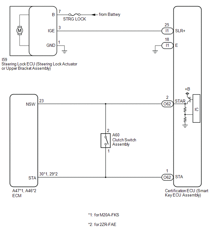
If an abnormal operation that may lead to a malfunction of the steering lock ECU (steering lock actuator or upper bracket assembly), or abnormal vehicle speed information is detected by the certification ECU (smart key ECU assembly), a system malfunction message is displayed on the multi-information display.
WIRING DIAGRAM

CAUTION / NOTICE / HINT
PROCEDURE
(a) Check for DTCs.
Body Electrical > Smart Key > Trouble Codes
Body Electrical > Power Source Control > Trouble Codes
|
Result
|
Proceed to
|
|
DTCs are not output
|
A
|
|
DTC U0129 is output.
|
B
|
|
DTC B2271, B2278, B2282, B2781, B2782, B2788 or U0155 is output.
|
C
|
|
A
|

|
|
|
2.
|
READ VALUE USING TECHSTREAM (STEERING LOCK)
|
(a) Connect the Techstream to the DLC3.
(b) Turn the engine switch on (IG).
(c) Turn the Techstream on.
(d) Enter the following menus: Body Electrical / Smart Key / Data List.
(e) Read the Data List according to the display on the Techstream.
Body Electrical > Smart Key > Data List
|
Tester Display
|
Measurement Item
|
Range
|
Normal Condition
|
Diagnostic Note
|
|
Sensor Value
|
History of malfunction of position sensor in steering lock ECU (steering lock actuator or upper bracket assembly) (DTC B2781 is stored)
|
OK or NG(Past)
|
OK: History of malfunction for the lock or unlock sensor in the steering lock ECU (steering lock actuator or upper bracket assembly) does not exist.
NG(Past): History of both the lock and unlock sensors in the steering lock ECU (steering lock actuator or upper bracket assembly) being on exists. (Under normal operation, neither sensor is on.)
|
When NG(Past) is displayed, either the position sensor in the steering lock ECU (steering lock actuator or upper bracket assembly) or the assembly itself may be malfunctioning.
|
Body Electrical > Smart Key > Data List
|
Tester Display
|
|
Sensor Value
|
OK:
OK is displayed on the Techstream.
|
OK
|

|
|
|
3.
|
READ VALUE USING TECHSTREAM (SENSOR BALUE)
|
(a) Enter the following menus: Body Electrical / Power Source Control / Data List.
(b) Read the Data List according to the display on the Techstream.
Body Electrical > Power Source Control > Data List
|
Tester Display
|
Measurement Item
|
Range
|
Normal Condition
|
Diagnostic Note
|
|
IG Circuit
|
IG relay coil circuit malfunction
|
OK or NG
|
OK: Circuit normal
NG: Circuit malfunctioning
|
-
Use this item to determine if the IG relay is malfunctioning.
-
When the engine cannot be started due to an IG relay malfunction, NG is displayed.
|
Body Electrical > Power Source Control > Data List
|
Tester Display
|
|
IG Circuit
|
|
Result
|
Proceed to
|
|
"NG" is displayed on the Techstream (for Manual Transaxle)
|
A
|
|
"NG" is displayed on the Techstream (except Manual Transaxle)
|
B
|
|
"OK" is displayed on the Techstream
|
C
|
|
A
|

|
|
|
4.
|
READ VALUE USING TECHSTREAM (NEUTRAL SW/ CLUTCH SW)
|
(a) Enter the following menus: Body Electrical / Power Source Control / Data List.
(b) Read the Data List according to the display on the Techstream.
Body Electrical > Power Source Control > Data List
|
Tester Display
|
Measurement Item
|
Range
|
Normal Condition
|
Diagnostic Note
|
|
Neutral SW/ Clutch SW
|
State of clutch pedal
|
OFF or ON
|
OFF: Clutch pedal released
ON: Clutch pedal depressed
|
-
Use this item to help determine if the clutch start switch is malfunctioning.
-
The engine cannot be started when this item is "OFF".
|
Body Electrical > Power Source Control > Data List
|
Tester Display
|
|
Neutral SW/ Clutch SW
|
OK:
The Techstream display changes correctly in response to the clutch pedal operation.
|
OK
|

|
|
|
5.
|
READ VALUE USING TECHSTREAM (VEHICLE SPEED SIGNAL)
|
(a) Enter the following menus: Body Electrical / Power Source Control / Data List.
(b) Read the Data List according to the display on the Techstream.
Body Electrical > Power Source Control > Data List
|
Tester Display
|
Measurement Item
|
Range
|
Normal Condition
|
Diagnostic Note
|
|
Vehicle Speed Signal
|
Vehicle being driven or stopped
|
Stop or Run
|
Stop: Vehicle stopped
Run: Vehicle being driven at 5 km/h (3 mph) or more
|
-
|
Body Electrical > Power Source Control > Data List
|
Tester Display
|
|
Vehicle Speed Signal
|
OK:
The Techstream display changes correctly in response to the vehicle condition.
| NG |

|
GO TO ELECTRONICALLY CONTROLLED BRAKE SYSTEM (HOW TO PROCEED WITH TROUBLESHOOTING)
w/ Electric Parking Brake System: Click here
![2019 - 2022 MY Corolla Corolla Hatchback GR Corolla [06/2018 - 09/2022]; BRAKE CONTROL / DYNAMIC CONTROL SYSTEMS: ELECTRONICALLY CONTROLLED BRAKE SYSTEM (for Gasoline Model with Electric Parking Brake System): HOW TO PROCEED WITH TROUBLESHOOTING](/t3Portal/stylegraphics/info.gif)
w/o Electric Parking Brake System: Click here
![2020 - 2022 MY Corolla Corolla Hatchback GR Corolla [01/2019 - 09/2022]; BRAKE CONTROL / DYNAMIC CONTROL SYSTEMS: ELECTRONICALLY CONTROLLED BRAKE SYSTEM (for Gasoline Model without Electric Parking Brake System): HOW TO PROCEED WITH TROUBLESHOOTING](/t3Portal/stylegraphics/info.gif)
|
|
OK
|

|
|
|
6.
|
CHECK HARNESS AND CONNECTOR (POWER SOURCE)
|
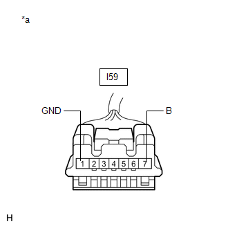
(a) Disconnect the I59 steering lock ECU (steering lock actuator or upper bracket assembly) connector.
|
(b) Measure the resistance according to the value(s) in the table below.
Standard Resistance:
|
Tester Connection
|
Condition
|
Specified Condition
|
|
I59-1 (GND) - Body ground
|
Always
|
Below 1 Ω
|
NOTICE:
If the result is not as specified, check for looseness in the ground cable connection.
|

|
|
*a
|
Front view of wire harness connector
(to Steering Lock ECU Steering Lock Actuator or Upper Bracket Assembly))
|
|
|
(c) Measure the voltage according to the value(s) in the table below.
Standard Voltage:
|
Tester Connection
|
Condition
|
Specified Condition
|
|
I59-7 (B) - Body ground
|
Always
|
11 to 14 V
|
| NG |

|
REPAIR OR REPLACE HARNESS OR CONNECTOR
|
|
OK
|

|
|
|
7.
|
CHECK STEERING LOCK ECU (STEERING LOCK ACTUATOR OR UPPER BRACKET ASSEMBLY)
|
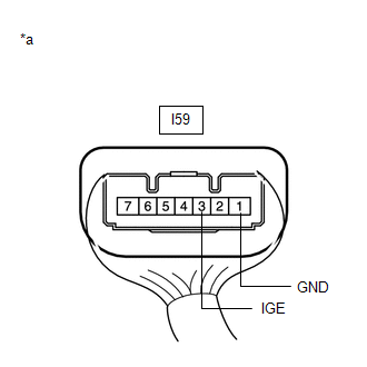
(a) Connect the I59 steering lock ECU (steering lock actuator or upper bracket assembly) connector.
|
(b) Measure the voltage according to the value(s) in the table below.
Standard Voltage:
|
Tester Connection
|
Condition
|
Specified Condition
|
|
I59-3 (IGE) - I59-1 (GND)
|
for Manual Transaxle
-
Steering lock motor operating when all conditions met, and then door opened:
-
The steering is unlocked.
-
The engine switch is off.
except Manual Transaxle
-
Steering lock motor operating when all conditions met, and then door opened:
-
The steering is unlocked.
-
The engine switch is off.
-
The shift lever is in P.
|
11 to 14 V → Below 1 V
|
|

|
|
*a
|
Component with harness connected
(Steering Lock ECU (Steering Lock Actuator or Upper Bracket Assembly))
|
|
|
|
NG
|

|
|
|
8.
|
CHECK HARNESS AND CONNECTOR (STEERING LOCK ECU (STEERING LOCK ACTUATOR OR UPPER BRACKET ASSEMBLY) - CERTIFICATION ECU (SMART KEY ECU ASSEMBLY))
|
(a) Disconnect the I59 steering lock ECU (steering lock actuator or upper bracket assembly) connector.
(b) Disconnect the I1 certification ECU (smart key ECU assembly) connector.
(c) Measure the resistance according to the value(s) in the table below.
Standard Resistance:
|
Tester Connection
|
Condition
|
Specified Condition
|
|
I59-3 (IGE) - I1-25 (SLR+)
|
Always
|
Below 1 Ω
|
|
I59-3 (IGE) or I1-25 (SLR+) - Other terminals and body ground
|
Always
|
10 kΩ or higher
|
| NG |

|
REPAIR OR REPLACE HARNESS OR CONNECTOR
|
|
OK
|

|
|
|
9.
|
CHECK STEERING LOCK ECU (STEERING LOCK ACTUATOR OR UPPER BRACKET ASSEMBLY)
|
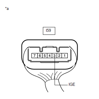
(a) Connect the I59 steering lock ECU (steering lock actuator or upper bracket assembly) connector.
|
(b) Measure the voltage according to the value(s) in the table below.
Standard Voltage:
|
Tester Connection
|
Condition
|
Specified Condition
|
|
I59-3 (IGE) - Body ground
|
Always
|
11 to 14 V
|
|

|
|
*a
|
Component with harness connected
(Steering Lock ECU (Steering Lock Actuator or Upper Bracket Assembly))
|
|
|
|
10.
|
INSPECT CLUTCH SWITCH ASSEMBLY
|
(a) Remove the clutch switch assembly.
Click here
![2020 - 2022 MY Corolla Corolla Hatchback GR Corolla [01/2019 - 09/2022]; CLUTCH: CLUTCH PEDAL SWITCH: REMOVAL](/t3Portal/stylegraphics/info.gif)
(b) Inspect the clutch switch assembly.
Click here
![2020 - 2023 MY Corolla Corolla Hatchback GR Corolla [01/2019 - 11/2022]; CLUTCH: CLUTCH PEDAL SWITCH: INSPECTION](/t3Portal/stylegraphics/info.gif)
|
OK
|

|
|
|
11.
|
CHECK HARNESS AND CONNECTOR (CERTIFICATION ECU (SMART KEY ECU ASSEMBLY) - CLUTCH SWITCH ASSEMBLY)
|
(a) Disconnect the O62 certification ECU (smart key ECU assembly) connector.
(b) Measure the resistance according to the value(s) in the table below.
Standard Resistance:
|
Tester Connection
|
Condition
|
Specified Condition
|
|
O62-2 (STAR) - A60-2
|
Always
|
Below 1 Ω
|
|
O62-2 (STAR) or A60-2 - Other terminals and body ground
|
Always
|
10 kΩ or higher
|
| NG |

|
REPAIR OR REPLACE HARNESS OR CONNECTOR
|
|
