| Last Modified: 05-13-2024 | 6.11:8.1.0 | Doc ID: RM100000001H978 |
| Model Year Start: 2020 | Model: Corolla | Prod Date Range: [01/2019 - 09/2022] |
| Title: HEATING / AIR CONDITIONING: AIR CONDITIONING SYSTEM (for HV Model): B1423; Open in Pressure Sensor Circuit / Abnormal Refrigerant Pressure; 2020 - 2022 MY Corolla Corolla HV [01/2019 - 09/2022] | ||
|
DTC |
B1423 |
Open in Pressure Sensor Circuit / Abnormal Refrigerant Pressure |
DESCRIPTION
This DTC is stored if refrigerant pressure on the high pressure side is extremely low (176 kPaG (1.8 kgf/cm2, 26 psi) or less*1, 196 kPaG (2.0 kgf/cm2, 28 psi) or less*2) or extremely high (3025 kPaG (30.8 kgf/cm2, 439 psi) or more*1, 2812 kPaG (28.7 kgf/cm2, 408 psi) or more*2). The air conditioner pressure sensor, which is installed to the high pressure side pipe to detect refrigerant pressure, sends a refrigerant pressure signal to the air conditioning amplifier assembly. The air conditioning amplifier assembly converts this signal to a pressure value according to the sensor characteristics and uses it to control the compressor.
- *1: for HFC-134a (R134a)
- *2: for HFO-1234yf (R1234yf)
|
DTC No. |
Detection Item |
DTC Detection Condition |
Trouble Area |
Memory |
|---|---|---|---|---|
|
B1423 |
Open in Pressure Sensor Circuit / Abnormal Refrigerant Pressure |
for HFC-134a (R134a):
for HFO-1234yf (R1234yf):
|
|
- |
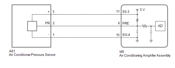
WIRING DIAGRAM

CAUTION / NOTICE / HINT
NOTICE:
HINT:
Make sure that the connector is properly connected. If it is not, securely connect it and check for DTCsagain.
PROCEDURE
|
1. |
CHECK FOR DTC |
(a) Connect the Techstream to the DLC3.
(b) Turn the power switch on (IG).
(c) Turn the Techstream on.
(d) Enter the following menus: Body Electrical / Air Conditioner / Data List.
(e) Check for DTCs.
Body Electrical > Air Conditioner > Trouble Codes
|
Result |
Proceed to |
|---|---|
|
B14B8 is not output |
A |
|
B14B8 is output |
B |
| B |

|
|
|
2. |
COMPARE REFRIGERANT GAS PRESSURE VALUES SHOWN ON TECHSTREAM AND MANIFOLD GAUGE SET |
(a) Connect the Techstream to the DLC3.
(b) Turn the power switch on (IG).
(c) Turn the Techstream on.
(d) Enter the following menus: Body Electrical / Air Conditioner / Data List.
(e) Read the Data List according to the display on the Techstream.
Body Electrical > Air Conditioner > Data List
|
Tester Display |
Measurement Item |
Range |
Normal Condition |
Diagnostic Note |
|---|---|---|---|---|
|
Regulator Pressure Sensor |
Air conditioner pressure sensor |
Min.: -456.68 kPaG Max.: 3294.37 kPaG |
Actual refrigerant pressure displayed |
|
Body Electrical > Air Conditioner > Data List
|
Tester Display |
|---|
|
Regulator Pressure Sensor |
(f) Install a manifold gauge set.
for HFC-134a (R134a): Click here
![2020 - 2025 MY Corolla Corolla Hatchback Corolla HV GR Corolla [01/2019 - ]; HEATING / AIR CONDITIONING: REFRIGERANT (for HFC-134a(R134a)): ON-VEHICLE INSPECTION](/t3Portal/stylegraphics/info.gif)
for HFO-1234yf (R1234yf): Click here
![2020 - 2025 MY Corolla Corolla Hatchback Corolla HV GR Corolla [01/2019 - ]; HEATING / AIR CONDITIONING: REFRIGERANT (for HFO-1234yf(R1234yf)): ON-VEHICLE INSPECTION](/t3Portal/stylegraphics/info.gif)
(g) Compare the values displayed in the Data List and on the manifold gauge set.
|
Result |
Proceed to |
|---|---|
|
Data List value and manifold gauge set value do not match and Data List value: 176 kPaG (1.8 kgf/cm2, 26 psi) or less*1, 196 kPaG (2.0 kgf/cm2, 28 psi) or less*2 |
A |
|
Data List value and manifold gauge set value do not match and Data List value: 3025 kPaG (30.8 kgf/cm2, 439 psi) or more*1, 2812 kPaG (28.7 kgf/cm2, 408 psi) or more*2 |
B |
|
Data List value matches manifold gauge set value |
C |
- *1: for HFC-134a (R134a)
- *2: for HFO-1234yf (R1234yf)
| B |

|
| C |

|
GO TO ON-VEHICLE INSPECTION (CHECK REFRIGERANT PRESSURE USING GAUGE) |
|
|
3. |
READ VALUE USING TECHSTREAM (REGULATOR PRESSURE SENSOR) |
(a) Connect the Techstream to the DLC3.
(b) Turn the power switch on (IG).
(c) Turn the Techstream on.
(d) Enter the following menus: Body Electrical / Air Conditioner / Data List.
(e) Read the Data List according to the display on the Techstream.
Body Electrical > Air Conditioner > Data List
|
Tester Display |
Measurement Item |
Range |
Normal Condition |
Diagnostic Note |
|---|---|---|---|---|
|
Regulator Pressure Sensor |
Air conditioner pressure sensor |
Min.: -456.68 kPaG Max.: 3294.37 kPaG |
Actual refrigerant pressure displayed |
|
Body Electrical > Air Conditioner > Data List
|
Tester Display |
|---|
|
Regulator Pressure Sensor |
OK:
Disconnecting the A61 connector of the air conditioner pressure sensor causes the Data List value to change.
|
Result |
Proceed to |
|---|---|
|
Regulator pressure sensor value changes |
A |
|
Regulator pressure sensor value does not change |
B |
| B |

|
|
|
4. |
CHECK TERMINAL VOLTAGE (AIR CONDITIONER PRESSURE SENSOR) |
|
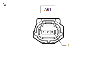
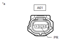
(a) Measure the voltage according to the value(s) in the table below. Standard Voltage:
|
|
| OK |

|
|
|
5. |
CHECK HARNESS AND CONNECTOR (AIR CONDITIONER PRESSURE SENSOR - AIR CONDITIONING AMPLIFIER ASSEMBLY) |
(a) Disconnect the I48 air conditioning amplifier assembly connector.
(b) Measure the resistance according to the value(s) in the table below.
Standard Resistance:
|
Tester Connection |
Condition |
Specified Condition |
|---|---|---|
|
A61-3 (+) - I48-11 (S5-3) |
Always |
Below 1 Ω |
| OK |

|
| NG |

|
REPAIR OR REPLACE HARNESS OR CONNECTOR |
|
6. |
CHECK TERMINAL VOLTAGE (AIR CONDITIONING AMPLIFIER ASSEMBLY) |
|
(a) Measure the voltage according to the value(s) in the table below. Standard Voltage:
|
|
| OK |

|
|
|
7. |
CHECK HARNESS AND CONNECTOR (AIR CONDITIONER PRESSURE SENSOR - AIR CONDITIONING AMPLIFIER ASSEMBLY) |
(a) Disconnect the I48 air conditioning amplifier assembly connector.
(b) Measure the resistance according to the value(s) in the table below.
Standard Resistance:
|
Tester Connection |
Condition |
Specified Condition |
|---|---|---|
|
A61-2 (PR) or I48-6 (PRE) - Other terminals and body ground |
Always |
10 kΩ or higher |
| OK |

|
| NG |

|
REPAIR OR REPLACE HARNESS OR CONNECTOR |
|
8. |
CHECK HARNESS AND CONNECTOR |
(a) Disconnect the A61 air conditioner pressure sensor connector.
(b) Measure the resistance according to the value(s) in the table below.
Standard Resistance:
|
Tester Connection |
Condition |
Specified Condition |
|---|---|---|
|
A61-1 (-) - Body ground |
Always |
Below 1 Ω |
| NG |

|
|
|
9. |
CHECK TERMINAL VOLTAGE |
|
(a) Measure the voltage according to the value(s) in the table below. Standard Voltage:
|
|
|
Result |
Proceed to |
|---|---|
|
5.25 V or higher |
A |
|
3.0 to 5.25 V |
B |
|
Below 3.0 V |
C |
| B |

|
| C |

|
|
|
10. |
CHECK HARNESS AND CONNECTOR (AIR CONDITIONER PRESSURE SENSOR - AIR CONDITIONING AMPLIFIER ASSEMBLY) |
(a) Disconnect the I48 air conditioning amplifier assembly connector.
(b) Measure the resistance according to the value(s) in the table below.
Standard Resistance:
|
Tester Connection |
Condition |
Specified Condition |
|---|---|---|
|
A61-2 (PR) or I48-6 (PRE) - Other terminals |
Always |
10 kΩ or higher |
| OK |

|
| NG |

|
REPAIR OR REPLACE HARNESS OR CONNECTOR |
|
11. |
CHECK INTERNAL CIRCUIT RESISTANCE (AIR CONDITIONING AMPLIFIER ASSEMBLY) |
(a) Measure the resistance according to the value(s) in the table below.
Standard Resistance:
|
Tester Connection |
Condition |
Specified Condition |
|---|---|---|
|
A61-3 (+) - A61-2 (PR) |
Power switch off |
180 to 220 kΩ |
HINT:
After turning the power switch off, wait at least 30 seconds before performing the measurement.
| OK |

|
|
|
12. |
CHECK HARNESS AND CONNECTOR (AIR CONDITIONER PRESSURE SENSOR - AIR CONDITIONING AMPLIFIER ASSEMBLY) |
(a) Disconnect the I48 air conditioning amplifier assembly connector.
(b) Measure the resistance according to the value(s) in the table below.
Standard Resistance:
|
Tester Connection |
Condition |
Specified Condition |
|---|---|---|
|
A61-2 (PR) or I48-6 (PRE) - A61-3 (+) or I48-11 (S5-3) |
Always |
10 kΩ or higher |
| OK |

|
| NG |

|
REPAIR OR REPLACE HARNESS OR CONNECTOR |
|
13. |
CHECK HARNESS AND CONNECTOR (AIR CONDITIONER PRESSURE SENSOR - AIR CONDITIONING AMPLIFIER ASSEMBLY) |
(a) Disconnect the I48 air conditioning amplifier assembly connector.
(b) Measure the resistance according to the value(s) in the table below.
Standard Resistance:
|
Tester Connection |
Condition |
Specified Condition |
|---|---|---|
|
A61-2 (PR) - I48-6 (PRE) |
Always |
Below 1 Ω |
| OK |

|
| NG |

|
REPAIR OR REPLACE HARNESS OR CONNECTOR |
|
14. |
CHECK HARNESS AND CONNECTOR (AIR CONDITIONER PRESSURE SENSOR - AIR CONDITIONING AMPLIFIER ASSEMBLY) |
(a) Disconnect the I48 air conditioning amplifier assembly connector.
(b) Measure the resistance according to the value(s) in the table below.
Standard Resistance:
|
Tester Connection |
Condition |
Specified Condition |
|---|---|---|
|
A61-1 (-) - I48-15 (SG-4) |
Always |
Below 1 Ω |
| OK |

|
| NG |

|
REPAIR OR REPLACE HARNESS OR CONNECTOR |
|
|
|


