| Last Modified: 07-31-2024 | 6.11:8.1.0 | Doc ID: RM100000001GYT2 |
| Model Year Start: 2020 | Model: Corolla Hatchback | Prod Date Range: [01/2019 - 11/2022] |
| Title: K313 (CVT): CONTINUOUSLY VARIABLE TRANSAXLE SYSTEM: Pattern Select Switch Sport Mode Circuit; 2020 - 2023 MY Corolla Corolla Hatchback [01/2019 - 11/2022] | ||
|
Pattern Select Switch Sport Mode Circuit |
DESCRIPTION
The ECM memory contains programs for normal and sport shift patterns.
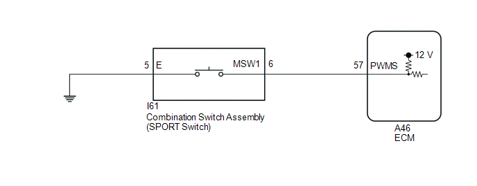
By following the programs corresponding to signals from the SPORT switch (combination switch assembly), park/neutral position switch assembly and various other sensors, the ECM switches the shift solenoid valves on and off, and controls the gear ratio.
WIRING DIAGRAM

CAUTION / NOTICE / HINT
NOTICE:
Perform initialization when parts related to the continuously variable transaxle system are replaced.
PROCEDURE
|
1. |
READ VALUE USING TECHSTREAM (PATTERN SWITCH (PWR/M)) |
(a) Connect the Techstream to the DLC3.
(b) Turn the ignition switch to ON.
(c) Turn the Techstream on.
(d) Enter the following menus: Powertrain / Engine and ECT / Data List.
(e) According to the display on the Techstream, read the Data List.
Powertrain > Engine and ECT > Data List
|
Tester Display |
Measurement Item |
Range |
Normal Condition |
Diagnostic Note |
|---|---|---|---|---|
|
Pattern Switch (PWR/M) |
SPORT mode switch status |
OFF or ON |
|
- |
|
Result |
Proceed to |
|---|---|
|
Data List value is normal |
A |
|
Data List value is not normal |
B |
| B |

|
|
|
2. |
REPLACE ECM |
(a) Replace the ECM.
| NEXT |

|
|
3. |
INSPECT COMBINATION SWITCH ASSEMBLY (SPORT SWITCH) |
|
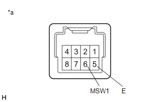
(a) Remove the combination switch assembly. |
|
(b) Measure the resistance according to the value(s) in the table below.
Standard Resistance:
|
Tester Connection |
Condition |
Specified Condition |
|---|---|---|
|
6 (MSW1) - 5 (E) |
SPORT switch (combination switch assembly) being pushed |
Below 50 Ω |
|
6 (MSW1) - 5 (E) |
SPORT switch (combination switch assembly) not being pushed |
10 kΩ or higher |
(c) Install the combination switch assembly.
| NG |

|
|
|
4. |
CHECK HARNESS AND CONNECTOR (COMBINATION SWITCH ASSEMBLY - BODY GROUND) |
(a) Disconnect the I61 combination switch assembly connector.
(b) Measure the resistance according to the value(s) in the table below.
Standard Resistance:
|
Tester Connection |
Condition |
Specified Condition |
|---|---|---|
|
I61-5 (E) - Body ground |
Always |
Below 1 Ω |
(c) Connect the I61 combination switch assembly connector.
| NG |

|
REPAIR OR REPLACE HARNESS OR CONNECTOR (COMBINATION SWITCH ASSEMBLY - BODY GROUND) |
|
|
5. |
CHECK HARNESS AND CONNECTOR (COMBINATION SWITCH ASSEMBLY - ECM) |
(a) Disconnect the A46 ECM connector.
(b) Measure the resistance according to the value(s) in the table below.
Standard Resistance:
|
Tester Connection |
Condition |
Specified Condition |
|---|---|---|
|
A46-57 (PWMS) - Body ground |
SPORT switch (combination switch assembly) being pushed |
Below 50 Ω |
|
A46-57 (PWMS) - Body ground |
SPORT switch (combination switch assembly) not being pushed |
10 kΩ or higher |
(c) Connect the A46 ECM connector.
| NG |

|
REPAIR OR REPLACE HARNESS OR CONNECTOR (PATTERN SELECT SWITCH ASSEMBLY - ECM) |
|
|
6. |
REPLACE ECM |
(a) Replace the ECM.
| NEXT |

|
|
|
|
![2020 - 2023 MY Corolla Corolla Hatchback [01/2019 - 11/2022]; K313 (CVT): CONTINUOUSLY VARIABLE TRANSAXLE SYSTEM: INITIALIZATION](/t3Portal/stylegraphics/info.gif)

