- DTC judgment completed
- System normal
| Last Modified: 07-31-2024 | 6.11:8.1.0 | Doc ID: RM100000001GYSQ |
| Model Year Start: 2020 | Model: Corolla Hatchback | Prod Date Range: [01/2019 - 11/2022] |
| Title: K313 (CVT): CONTINUOUSLY VARIABLE TRANSAXLE SYSTEM: P1585; Acceleration Sensor Circuit; 2020 - 2023 MY Corolla Corolla Hatchback [01/2019 - 11/2022] | ||
|
DTC |
P1585 |
Acceleration Sensor Circuit |
DESCRIPTION
The ECM determines the vehicle inclination based on a signal from the yaw rate and acceleration sensor. If a malfunction is determined in the yaw rate and acceleration sensor (airbag sensor assembly) based on a malfunction signal from the skid control ECU (brake actuator assembly), the ECM stores this DTC.
HINT:
- The signal of the yaw rate and acceleration sensor (airbag sensor assembly) is sent to the skid control ECU (brake actuator assembly) via the CAN communication system.
- If CAN communication DTCs are output, perform troubleshooting for those DTCs first.
|
DTC No. |
Detection Item |
DTC Detection Condition |
Trouble Area |
MIL |
Memory |
|---|---|---|---|---|---|
|
P1585 |
Acceleration Sensor Circuit |
Any of the following conditions are met for 3 seconds or more (1-trip detection logic):
|
|
Does not come on |
DTC stored |
DTC Detection Condition Patterns:
|
Vehicle Condition |
||||||
|---|---|---|---|---|---|---|
|
Pattern 1 |
Pattern 2 |
Pattern 3 |
Pattern 4 |
Pattern 5 |
||
|
Diagnostic Condition |
The ignition switch is ON. |
○ |
○ |
○ |
○ |
○ |
|
Malfunction Condition |
The output value of the yaw rate and acceleration sensor remains at -1.5 G or less, or 1.5 G or more for at least 1.2 seconds. |
○ |
- |
- |
- |
- |
|
The yaw rate and acceleration sensor power source voltage is at 4.4 V or less, or 5.6 V or higher for 1.2 seconds or more. |
- |
○ |
- |
- |
- |
|
|
No signal from the yaw rate and acceleration sensor is detected 7 times or more. |
- |
- |
○ |
- |
- |
|
|
With the vehicle stopped, the difference between GL1 and GL2 does not become less than 0.4 G within 60 seconds after exceeding 0.6 G. |
- |
- |
- |
○ |
- |
|
|
A yaw rate and acceleration sensor power source voltage malfunction signal is received for at least 10 seconds with the vehicle speed at 3 km/h (1.8 mph) or more. |
- |
- |
- |
- |
○ |
|
|
Duration |
3 seconds or more |
3 seconds or more |
3 seconds or more |
3 seconds or more |
3 seconds or more |
|
|
Detection Logic |
1-trip detection logic |
1-trip detection logic |
1-trip detection logic |
1-trip detection logic |
1-trip detection logic |
|
HINT:
This DTC is stored when either of the above detection patterns is met.
CONFIRMATION DRIVING PATTERN
CAUTION:
When performing the confirmation driving pattern, obey all speed limits and traffic laws.
HINT:
After repairs have been completed, clear the DTCs and then check that the vehicle has returned to normal by performing the following All Readiness check procedure.
- Connect the Techstream to the DLC3.
- Turn the ignition switch to ON and turn the Techstream on.
- Clear the DTCs (even if no DTCs are stored, perform the clear DTC procedure).
- Turn the ignition switch off and wait for 2 minutes or more.
- Turn the ignition switch to ON and turn the Techstream on.
- Start the engine.
- Drive the vehicle while accelerating and decelerating repeatedly for several minutes.
- Stop the vehicle.
- Enter the following menus: Powertrain / Engine and ECT / Utility / All Readiness.
- Input the DTC: P1585.
-
Check the DTC judgment result.
Techstream Display
Description
NORMAL
ABNORMAL
- DTC judgment completed
- System abnormal
INCOMPLETE
- DTC judgment not completed
- Perform driving pattern after confirming DTC enabling conditions
N/A
- Unable to perform DTC judgment
- Number of DTCs which do not fulfill DTC preconditions has reached ECU memory limit
HINT:
- If the judgment result shows NORMAL, the system is normal.
- If the judgment result shows ABNORMAL, the system has a malfunction.
- If the judgment result shows INCOMPLETE or N/A, perform the Confirmation Driving Pattern and check the DTC judgment result again.
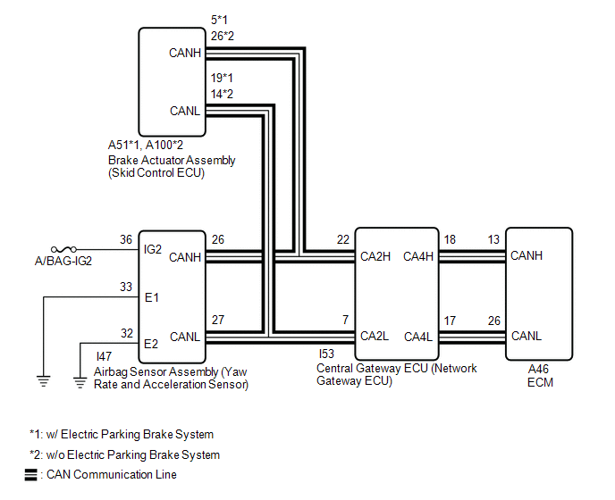
WIRING DIAGRAM

CAUTION / NOTICE / HINT
CAUTION:
-
Strictly observe posted speed, limits, traffic laws and road conditions.

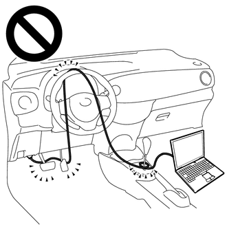
- Do not drive the vehicle with the cable of the Techstream contacting the pedals, shift lever or steering wheel.
- Driving the vehicle with the cable of the Techstream contacting these areas could impede vehicle control, resulting in a serious accident.
-
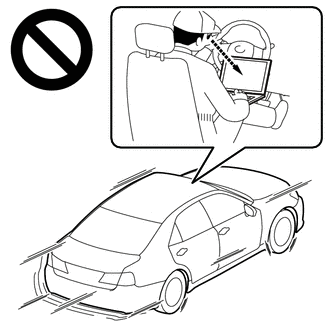
Do not operate the Techstream while driving the vehicle.

- Operating the Techstream while driving the vehicle will prevent you from paying sufficient attention to vehicle surroundings, and could result in a serious accident.
NOTICE:
PROCEDURE
|
1. |
CHECK DTC OUTPUT |
(a) Connect the Techstream to the DLC3.
(b) Turn the ignition switch to ON.
(c) Turn the Techstream on.
(d) Check for DTCs.
Powertrain > Engine and ECT > Trouble Codes
|
Result |
Proceed to |
|---|---|
|
DTC U0129 is not output |
A |
|
DTC U0129 is output |
B |
| B |

|
|
|
2. |
READ VALUE USING TECHSTREAM (G SENSOR) |
(a) Connect the Techstream to the DLC3.
(b) Turn the ignition switch to ON.
(c) Turn the Techstream on.
(d) Enter the following menus: Powertrain / Engine and ECT / Data List.
(e) According to the display on the Techstream, read the Data List.
Powertrain > Engine and ECT > Data List
|
Tester Display |
Measurement Item |
Range |
Normal Condition |
Diagnostic Note |
|---|---|---|---|---|
|
G Sensor |
Converted output voltage of yaw rate and acceleration sensor |
Min.: 0 V Max.: 79.998 V |
|
- |
Powertrain > Engine and ECT > Data List
|
Tester Display |
|---|
|
G Sensor |
|
Result |
Proceed to |
|---|---|
|
Data List value is not normal |
A |
|
Data List value is normal |
B |
| B |

|
|
|
3. |
REPLACE AIRBAG SENSOR ASSEMBLY |
(a) Replace the airbag sensor assembly.
| NEXT |

|
|
|
|
![2020 - 2023 MY Corolla Corolla Hatchback [01/2019 - 11/2022]; K313 (CVT): CONTINUOUSLY VARIABLE TRANSAXLE SYSTEM: INITIALIZATION](/t3Portal/stylegraphics/info.gif)
