- DTC judgment completed
- System normal
| Last Modified: 07-31-2024 | 6.11:8.1.0 | Doc ID: RM100000001GYSK |
| Model Year Start: 2020 | Model: Corolla Hatchback | Prod Date Range: [01/2019 - 11/2022] |
| Title: K313 (CVT): CONTINUOUSLY VARIABLE TRANSAXLE SYSTEM: P0717,P07BF,P07C0; Input/Turbine Speed Sensor "A" Circuit No Signal; 2020 - 2023 MY Corolla Corolla Hatchback [01/2019 - 11/2022] | ||
|
DTC |
P0717 |
Input/Turbine Speed Sensor "A" Circuit No Signal |
|
DTC |
P07BF |
Input/Turbine Speed Sensor "A" Circuit Low |
|
DTC |
P07C0 |
Input/Turbine Speed Sensor "A" Circuit High |
DESCRIPTION
The ECM receives a signal from the transmission revolution sensor (NT) installed to the continuously variable transaxle assembly to control the lock-up engagement pressure and forward and reverse clutch pressure.
The transmission revolution sensor (NT) detects the input turbine speed and sends a signal to the ECM.
|
DTC No. |
Detection Item |
DTC Detection Condition |
Trouble Area |
MIL |
Memory |
|---|---|---|---|---|---|
|
P0717 |
Input/Turbine Speed Sensor "A" Circuit No Signal |
All of the following conditions are met (1-trip detection logic):
|
|
Comes on |
DTC stored |
|
P07BF |
Input/Turbine Speed Sensor "A" Circuit Low |
There is no malfunction in the transmission revolution sensor (NT) signals, and the transmission revolution sensor (NT) output voltage is less than 0.2 V for 2 seconds (1-trip detection logic). |
|
Comes on |
DTC stored |
|
P07C0 |
Input/Turbine Speed Sensor "A" Circuit High |
There is no malfunction in the transmission revolution sensor (NT) signals, and the transmission revolution sensor (NT) output voltage is higher than 1.8 V for 2 seconds (1-trip detection logic). |
|
Comes on |
DTC stored |
MONITOR DESCRIPTION
The transmission revolution sensor (NT) is used to detect the input turbine speed. The ECM determines the necessary gear ratio based on a comparison of the transmission revolution sensor (NT) (input turbine speed) and transmission revolution sensor (NOUT) (output shaft speed) signals.
When the output shaft speed is higher than the expected value and the input turbine speed is less than 300 rpm while driving with the shift lever in D, the ECM will determine that the transmission revolution sensor (NT) is malfunctioning, illuminate the MIL and store a DTC.
MONITOR STRATEGY
|
Related DTCs |
P0717: Input speed sensor (NT) / Verify pulse input P07BF: Input speed sensor (NT) / Range check (Low voltage) P07C0: Input speed sensor (NT) / Range check (High voltage) |
|
Required sensors/Components |
Transmission revolution sensor (NT) |
|
Frequency of operation |
Continuous |
|
Duration |
2 seconds |
|
MIL operation |
Immediately |
|
Sequence of operation |
None |
TYPICAL ENABLING CONDITIONS
All
|
Battery voltage |
8 V or more |
|
Time after battery voltage is 8 V or more |
0.5 seconds or more |
|
Write inhibit |
Permit |
|
Time after write status forbiddance to permit |
0.5 seconds or more |
|
Ignition switch |
ON |
|
Time after ignition switch OFF to ON |
0.5 seconds or more |
|
Starter |
OFF |
|
Time after starter ON to OFF |
0.5 seconds or more |
P0717:
|
Park/neutral position switch |
OFF |
|
Output shaft revolution |
300 rpm or more |
|
R range position switch |
OFF |
|
Transmission range switch circuit fail (P0705) (Pending + MIL) |
Not detected |
|
Engine |
Running |
|
Turbine speed sensor range check fail (P07BF, P07C0) (Pending / MIL) |
Not detected |
|
Output speed sensor revolution |
1100 rpm or more |
|
One of the following conditions is met: |
- |
|
- Command to shift solenoid |
OFF |
|
- Command to torque converter clutch solenoid |
ON |
|
Shift solenoid circuit fail (P099B, P099C) (Pending + MIL) |
Not detected |
|
Torque converter clutch solenoid circuit fail (P2769, P2770) (Pending + MIL) |
Not detected |
|
Pressure control solenoid circuit fail (P2822, P282B) (Pending + MIL) |
Not detected |
P07BF, P07C0:
|
Turbine speed sensor pulse input fail (P0717) (Pending / MIL) |
Not detected |
TYPICAL MALFUNCTION THRESHOLDS
P0717:
|
Turbine speed (Input speed) sensor revolution |
Less than 300 rpm |
P07BF:
|
Turbine speed (Input speed) sensor output voltage |
Less than 0.2 V |
P07C0:
|
Turbine speed (Input speed) sensor output voltage |
More than 1.8 V |
COMPONENT OPERATING RANGE
P0717:
|
Turbine speed (Input speed) sensor revolution |
300 rpm or more |
P07BF, P07C0:
|
Turbine speed (Input speed) sensor output voltage |
0.2 to 1.8 V |
CONFIRMATION DRIVING PATTERN
CAUTION:
When performing the confirmation driving pattern, obey all speed limits and traffic laws.
HINT:
- Connect the Techstream to the DLC3.
- Turn the ignition switch to ON and turn the Techstream on.
- Clear the DTCs (even if no DTCs are stored, perform the clear DTC procedure).
- Turn the ignition switch off and wait for 2 minutes or more.
- Turn the ignition switch to ON and turn the Techstream on.
- Start the engine.
-
Perform the D Position Shift Test inspection in Road Test. [*1]
HINT:
[*1]: Normal judgment procedure.
The normal judgment procedure is used to complete DTC judgment and also used when clearing permanent DTCs.
- Stop the vehicle.
- Enter the following menus: Powertrain / Engine and ECT / Utility / All Readiness.
- Input the DTC: P0717, P07BF or P07C0.
-
Check the DTC judgment result.
Techstream Display
Description
NORMAL
ABNORMAL
- DTC judgment completed
- System abnormal
INCOMPLETE
- DTC judgment not completed
- Perform driving pattern after confirming DTC enabling conditions
N/A
- Unable to perform DTC judgment
- Number of DTCs which do not fulfill DTC preconditions has reached ECU memory limit
HINT:
- If the judgment result shows NORMAL, the system is normal.
- If the judgment result shows ABNORMAL, the system has a malfunction.
- If the judgment result shows INCOMPLETE or N/A, perform the normal judgment procedure again.
WIRING DIAGRAM
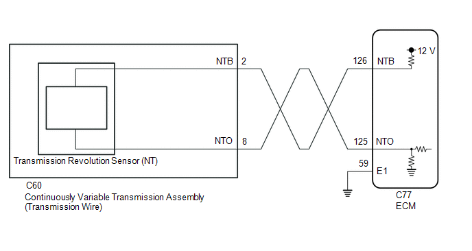
CAUTION / NOTICE / HINT
CAUTION:
-
Strictly observe posted speed, limits, traffic laws and road conditions.
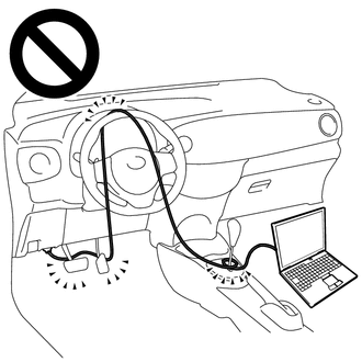
- Do not drive the vehicle with the cable of the Techstream contacting the pedals, shift lever or steering wheel.
- Driving the vehicle with the cable of the Techstream contacting these areas could impede vehicle control, resulting in a serious accident.
-
Do not operate the Techstream while driving the vehicle.
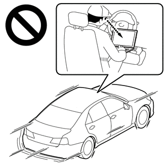
- Operating the Techstream while driving the vehicle will prevent you from paying sufficient attention to vehicle surroundings, and could result in a serious accident.
NOTICE:
PROCEDURE
|
1. |
READ VALUE USING TECHSTREAM (SPD (NT) AND NT SENSOR VOLTAGE) |
(a) Connect the Techstream to the DLC3.
(b) Turn the ignition switch to ON.
(c) Turn the Techstream on.
(d) Enter the following menus: Powertrain / Engine and ECT / Data List.
(e) According to the display on the Techstream, read the Data List.
Powertrain > Engine and ECT > Data List
|
Tester Display |
Measurement Item |
Range |
Normal Condition |
Diagnostic Note |
|---|---|---|---|---|
|
SPD (NT) |
Input turbine speed (NT) |
Min.: 0 rpm Max.: 65535 rpm |
|
Data is displayed in increments of 50 rpm. |
|
NT Sensor Voltage |
Transmission revolution sensor (NT) output voltage |
Min.: 0.000 V Max.: 4.999 V |
0.1 to 1.9 V: Engine idling (Vehicle stopped with shift lever in P or N) |
- |
Powertrain > Engine and ECT > Data List
|
Tester Display |
|---|
|
SPD (NT) |
|
NT Sensor Voltage |
|
Result |
Proceed to |
|---|---|
|
Data List value is not normal |
A |
|
Data List value is normal |
B |
| B |

|
|
|
2. |
CHECK HARNESS AND CONNECTOR (TRANSMISSION WIRE - ECM) |
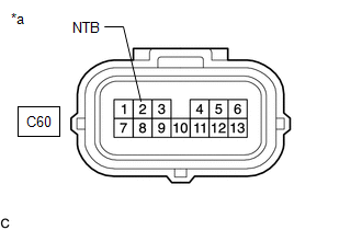
(a) Disconnect the C60 transmission wire connector.
(b) Disconnect the C77 ECM connector.
(c) Measure the resistance according to the value(s) in the table below.
Standard Resistance:
|
Tester Connection |
Condition |
Specified Condition |
|---|---|---|
|
C60-8 (NTO) - C77-125 (NTO) |
Always |
Below 1 Ω |
|
C60-2 (NTB) - C77-126 (NTB) |
Always |
Below 1 Ω |
|
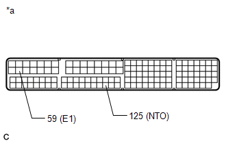
C77-59 (E1) - Body ground |
Always |
Below 1 Ω |
|
C60-8 (NTO) or C77-125 (NTO) - Body ground and other terminals |
Always |
10 kΩ or higher |
|
C60-2 (NTB) or C77-126 (NTB) - Body ground and other terminals |
Always |
10 kΩ or higher |
(d) Connect the C77 ECM connector.
(e) Connect the C60 transmission wire connector.
| NG |

|
REPAIR OR REPLACE HARNESS OR CONNECTOR (TRANSMISSION WIRE - ECM) |
|
|
3. |
CHECK ECM |
|
(a) Disconnect the C60 transmission wire connector. |
|
(b) Turn the ignition switch to ON.
(c) Measure the voltage according to the value(s) in the table below.
Standard Voltage:
|
Tester Connection |
Condition |
Specified Condition |
|---|---|---|
|
C60-2 (NTB) - Body ground |
Ignition switch ON |
11 to 14 V |
(d) Turn the ignition switch off.
(e) Connect the C60 transmission wire connector.
|
(f) Disconnect the C77 ECM connector. |
|
(g) Measure the resistance according to the value(s) in the table below.
Standard Resistance:
|
Tester Connection |
Condition |
Specified Condition |
|---|---|---|
|
125 (NTO) - 59 (E1) |
Always |
99 to 101 Ω |
| NG |

|
|
|
4. |
REPLACE CONTINUOUSLY VARIABLE TRANSAXLE ASSEMBLY |
(a) Replace the continuously variable transaxle assembly.
| NEXT |

|
|
5. |
REPLACE ECM |
(a) Replace the ECM.
| NEXT |

|
|
6. |
REPLACE ECM |
(a) Replace the ECM.
| NEXT |

|
|
|
|
![2020 - 2023 MY Corolla Corolla Hatchback [01/2019 - 11/2022]; K313 (CVT): CONTINUOUSLY VARIABLE TRANSAXLE SYSTEM: DTC CHECK / CLEAR](/t3Portal/stylegraphics/info.gif)

