| Last Modified: 01-27-2025 | 6.11:8.1.0 | Doc ID: RM100000001GWZ4 |
| Model Year Start: 2020 | Model: Corolla Hatchback | Prod Date Range: [01/2019 - 03/2019] |
| Title: STEERING COLUMN: STEERING WHEEL (except G16E-GTS): REMOVAL; 2020 MY Corolla Corolla Hatchback Corolla HV [01/2019 - 03/2019] | ||
REMOVAL
CAUTION / NOTICE / HINT
The necessary procedures (adjustment, calibration, initialization, or registration) that must be performed after parts are removed and installed, or replaced during steering wheel assembly removal/installation are shown below.
Necessary Procedures After Parts Removed/Installed/Replaced (for HV Model)
|
Replaced Part or Performed Procedure |
Necessary Procedure |
Effect/Inoperative Function when Necessary Procedure not Performed |
Link |
|---|---|---|---|
|
Disconnect cable from negative auxiliary battery terminal |
Perform steering sensor zero point calibration |
Lane Control System |
|
|
Pre-collision System |
Necessary Procedures After Parts Removed/Installed/Replaced (for Gasoline Model)
|
Replaced Part or Performed Procedure |
Necessary Procedure |
Effect/Inoperative Function when Necessary Procedure not Performed |
Link |
|---|---|---|---|
| *1: for Hatchback | |||
|
Disconnect cable from negative auxiliary battery terminal |
Perform steering sensor zero point calibration |
Lane Control System |
|
|
Pre-collision System |
|||
|
Lighting System (w/ AFS)(EXT) |
|||
|
Initialize back door lock*1 |
Power Door Lock Control System |
|
|
NOTICE:
- Do not remove/install the spiral cable with sensor sub-assembly with the auxiliary battery connected and the ignition switch (for Gasoline Model) or power switch (for HV Model) on (IG).
- Do not rotate the spiral cable with sensor sub-assembly without the steering wheel assembly installed, with the auxiliary battery connected and the ignition switch (for Gasoline Model) or power switch (for HV Model) on (IG).
- Ensure that the steering wheel assembly is installed and aligned straight when inspecting the steering sensor.
for HV Model:
- After the power switch is turned off, the radio and display receiver assembly records various types of memory and settings. As a result, after turning the power switch off, make sure to wait at least 85 seconds before disconnecting the cable from the negative (-) auxiliary battery terminal. (for Audio and Visual System (for HV Model))
for Gasoline Model:
- After the ignition switch is turned off, the radio and display receiver assembly records various types of memory and settings. As a result, after turning the ignition switch off, make sure to wait at least 85 seconds before disconnecting the cable from the negative (-) battery terminal. (for Audio and Visual System (for Gasoline Model))
- After the engine switch is turned off, the radio and display receiver assembly records various types of memory and settings. As a result, after turning the engine switch off, make sure to wait at least 85 seconds before disconnecting the cable from the negative (-) battery terminal. (for Navigation System)
PROCEDURE
1. ALIGN FRONT WHEELS FACING STRAIGHT AHEAD
2. REMOVE HORN BUTTON ASSEMBLY
Click here
![2020 MY Corolla Corolla Hatchback Corolla HV [01/2019 - 03/2019]; SUPPLEMENTAL RESTRAINT SYSTEMS: STEERING PAD (except G16E-GTS): REMOVAL](/t3Portal/stylegraphics/info.gif)
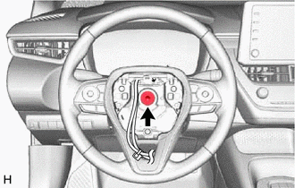
3. REMOVE STEERING WHEEL ASSEMBLY
(a) Disconnect each connector.
|
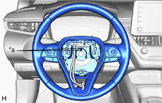
(b) Using a 10 mm hexagon socket wrench, remove the steering wheel assembly set bolt. |
|
|
(c) Put matchmarks on the steering wheel assembly and steering main shaft. |
|
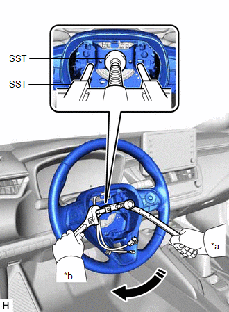
(d) Temporarily install the steering wheel assembly set bolt.
NOTICE:
Do not overtighten the steering wheel assembly set bolt.
|
(e) Using SST, separate the steering wheel assembly. SST: 09950-50013 09951-05010 09952-05010 09953-05020 09954-05031 09957-04010 SST: 09950-60011 09951-00330 NOTICE: Apply a small amount of grease to the threads and tip of SST (09953-05020) before use. |
|
(f) Remove the steering wheel assembly set bolt and steering wheel assembly.
4. REMOVE STEERING PAD SWITCH ASSEMBLY
Click here
5. REMOVE SHIFT PADDLE SWITCH (TRANSMISSION SHIFT SWITCH ASSEMBLY) (w/ Shift Paddle Switch)
Click here
|
|
|