| Last Modified: 07-31-2024 | 6.11:8.1.0 | Doc ID: RM100000001GWZ0 |
| Model Year Start: 2020 | Model: GR Corolla | Prod Date Range: [01/2019 - 09/2022] |
| Title: STEERING COLUMN: STEERING COLUMN ASSEMBLY: DISASSEMBLY; 2020 - 2022 MY Corolla Corolla Hatchback Corolla HV GR Corolla [01/2019 - 09/2022] | ||
DISASSEMBLY
CAUTION / NOTICE / HINT
NOTICE:
- Before replacing the steering lock actuator assembly, refer to Registration (w/ Smart Key System).
- Do not drop the power steering ECU with motor assembly, strike it with tools or subject it to impacts.
- If the power steering ECU with motor assembly is subjected to an impact, replace it with a new one.
- Do not pull the wire harness.
- Do not allow any moisture to come into contact with the power steering ECU with motor assembly.
- Do not loosen any bolts not mentioned in the procedure.
- Do not allow any foreign matter to contaminate the power steering ECU with motor assembly.
PROCEDURE
1. REMOVE UPPER STEERING COLUMN BRACKET WITH SWITCH ASSEMBLY (w/o Smart Key System)
(a) Secure the steering column assembly in a vise between aluminum plates.
NOTICE:
Do not overtighten the vise.
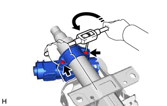
(b) Using a drill, drill a hole in the 2 steering lock set bolts and insert a screw extractor.
|
(c) Using the screw extractor, remove the 2 steering lock set bolts, upper steering column clamp and upper steering column bracket with switch assembly. |
|
2. REMOVE STEERING LOCK ACTUATOR ASSEMBLY (w/ Smart Key System)
(a) Secure the steering column assembly in a vise between aluminum plates.
NOTICE:
Do not overtighten the vise.
|
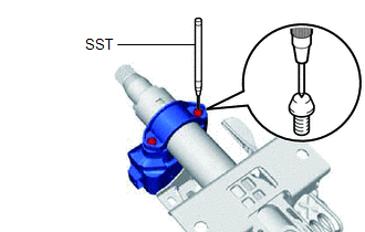
(b) Using SST, strike a punch mark for drilling in the center of the steering lock set bolt. SST: 09622-00010 NOTICE: When striking the punch mark, in order to prevent impact force from being applied to the steering lock actuator assembly, do not use a normal center punch. |
|
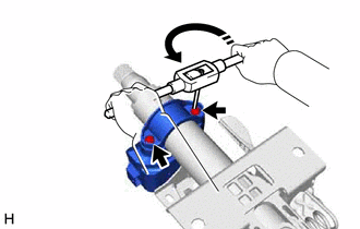
(c) Using a drill, drill a hole in the 2 steering lock set bolts and insert a screw extractor.
|
(d) Using the screw extractor, remove the 2 steering lock set bolts, upper steering column clamp and steering lock actuator assembly. |
|
3. REMOVE POWER STEERING ECU WITH MOTOR ASSEMBLY
4. REMOVE ELECTRIC POWER STEERING MOTOR SHAFT DAMPER
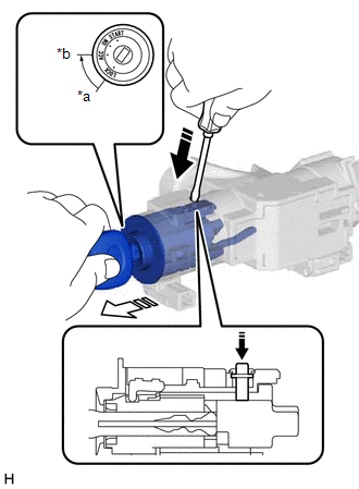
5. REMOVE IGNITION SWITCH LOCK CYLINDER ASSEMBLY (w/o Smart Key System)
(a) Turn the ignition switch to ACC.
|
*a |
LOCK |
|
*b |
ACC |

|
Push |

|
Pull |
(b) Insert the tip of a screwdriver into the hole in the upper steering column bracket assembly, as shown in the illustration, and pull out the ignition switch lock cylinder assembly.
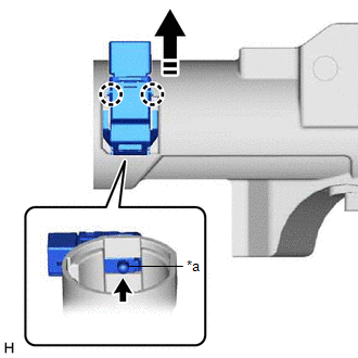
6. REMOVE UN-LOCK WARNING SWITCH ASSEMBLY (w/o Smart Key System)
(a) Remove the un-lock warning switch assembly by pushing up the center part and releasing the 2 claws.
|
*a |
Center Part |

|
Slide in this direction |
HINT:
Slide the un-lock warning switch assembly in the direction shown by the arrow in the illustration to remove it.
7. REMOVE IGNITION OR STARTER SWITCH ASSEMBLY (w/o Smart Key System)
|
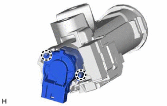
(a) Disengage the 2 claws and remove the ignition or starter switch assembly from the upper steering column bracket assembly. |
|
|
|
|
![2020 MY Corolla Corolla HV [01/2019 - 04/2020]; THEFT DETERRENT / KEYLESS ENTRY: SMART KEY SYSTEM (for Start Function, HV Model): REGISTRATION](/t3Portal/stylegraphics/info.gif)
