| Last Modified: 05-13-2024 | 6.11:8.1.0 | Doc ID: RM100000001GWDZ |
| Model Year Start: 2020 | Model: GR Corolla | Prod Date Range: [01/2019 - 03/2019] |
| Title: CELLULAR COMMUNICATION: TELEPHONE AND GPS ANTENNA (for Roof Side): REMOVAL; 2020 MY Corolla Corolla Hatchback Corolla HV GR Corolla [01/2019 - 03/2019] | ||
REMOVAL
CAUTION / NOTICE / HINT
The necessary procedures (adjustment, calibration, initialization or registration) that must be performed after parts are removed and installed, or replaced during telephone and GPS antenna assembly removal/installation are shown below.
Necessary Procedure After Parts Removed/Installed/Replaced (for Sedan, HV Model)
|
Replaced Part or Performed Procedure |
Necessary Procedure |
Effect/Inoperative Function When Necessary Procedures are not Performed |
Link |
|---|---|---|---|
|
Disconnect cable from negative (-) auxiliary battery terminal |
Perform steering sensor zero point calibration |
Lane Control System |
|
|
Pre-collision System |
CAUTION:
Some of these service operations affect the SRS airbag system. Read the precautionary notices concerning the SRS airbag system before servicing.
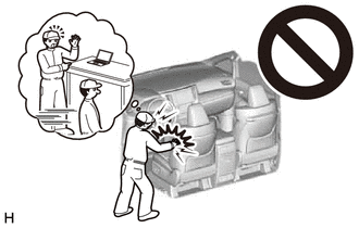
NOTICE:
After the power switch is turned off, the radio and display receiver assembly records various types of memory and settings. As a result, after turning the power switch off, make sure to wait at least 85 seconds before disconnecting the cable from the negative (-) auxiliary battery terminal. (for Audio and Visual System (for HV Model))
Necessary Procedure After Parts Removed/Installed/Replaced (for Sedan, Gasoline Model)
|
Replaced Part or Performed Procedure |
Necessary Procedure |
Effect/Inoperative Function When Necessary Procedures are not Performed |
Link |
|---|---|---|---|
| *1: for Hatchback | |||
|
Disconnect cable from negative (-) battery terminal |
Perform steering sensor zero point calibration |
Lane Control System |
|
|
Pre-collision System |
|||
|
Lighting System (w/ AFS)(EXT) |
|||
|
Initialize back door lock*1 |
Power Door Lock Control System |
||
CAUTION:
Some of these service operations affect the SRS airbag system. Read the precautionary notices concerning the SRS airbag system before servicing.

NOTICE:
- After the ignition switch is turned off, the radio and display receiver assembly records various types of memory and settings. As a result, after turning the ignition switch off, make sure to wait at least 85 seconds before disconnecting the cable from the negative (-) battery terminal. (for Audio and Visual System (for Gasoline Model))
- After the engine switch is turned off, the radio and display receiver assembly records various types of memory and settings. As a result, after turning the engine switch off, make sure to wait at least 85 seconds before disconnecting the cable from the negative (-) battery terminal. (for Navigation System)
PROCEDURE
1. REMOVE ROOF HEADLINING ASSEMBLY (for Hatchback)
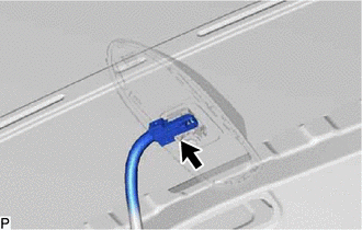
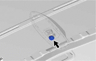
2. REMOVE TELEPHONE AND GPS ANTENNA ASSEMBLY WITH COVER (for Hatchback)
|
(a) Disconnect the connector. |
|
|
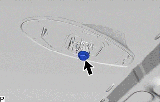
(b) Remove the bolt. |
|
(c) Remove the washer and holder as shown in the illustration.
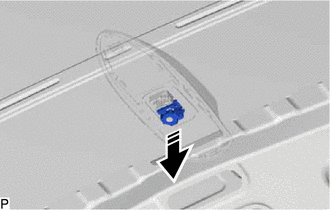

|
Remove in this Direction |
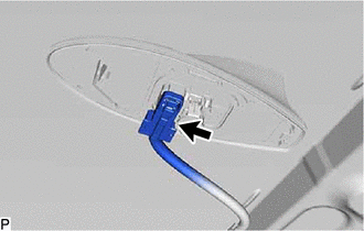
(d) Remove the telephone and GPS antenna assembly with cover as shown in the illustration.
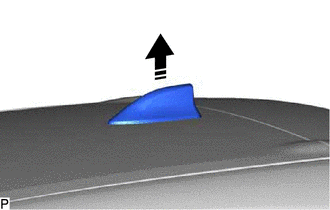

|
Remove in this Direction |
3. REMOVE TELEPHONE AND GPS ANTENNA ASSEMBLY (for Hatchback)
(a) Pull the telephone and GPS antenna assembly in the direction indicated by the arrow (1) shown in the illustration to disengage the 5 claws and 2 guides.
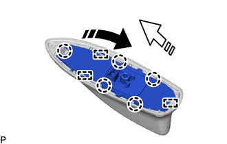

|
Remove in this Direction (1) |

|
Remove in this Direction (2) |
(b) Pull the telephone and GPS antenna assembly in the direction indicated by the arrow (2) shown in the illustration to disengage the guide and remove the telephone and GPS antenna assembly.
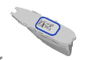
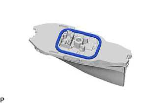
(c) When reusing the telephone and GPS antenna assembly:
|
(1) Remove the seal. |
|
4. REMOVE ROOF HEADLINING ASSEMBLY (for Sedan)
5. REMOVE TELEPHONE AND GPS ANTENNA ASSEMBLY WITH COVER (for Sedan)
|
(a) Disconnect the connector. |
|
|
(b) Remove the bolt. |
|
(c) Remove the washer and holder as shown in the illustration.
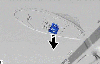

|
Remove in this Direction |
(d) Remove the telephone and GPS antenna assembly with cover as shown in the illustration.
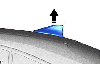

|
Remove in this Direction |
6. REMOVE TELEPHONE AND GPS ANTENNA ASSEMBLY (for Sedan)
(a) Pull the telephone and GPS antenna assembly in the direction indicated by the arrow (1) shown in the illustration to disengage the 3 claws and 2 guides.
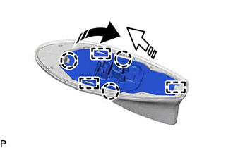

|
Remove in this Direction (1) |

|
Remove in this Direction (2) |
(b) Pull the telephone and GPS antenna assembly in the direction indicated by the arrow (2) shown in the illustration to disengage the guide and remove the telephone and GPS antenna assembly.
(c) When reusing the telephone and GPS antenna assembly:
|
(1) Remove the seal. |
|
|
|
|
![2020 - 2022 MY Corolla Corolla HV [01/2019 - 09/2022]; PRE-COLLISION: PRE-COLLISION SYSTEM (for HV Model): INITIALIZATION](/t3Portal/stylegraphics/info.gif)
