| Last Modified: 07-31-2024 | 6.11:8.1.0 | Doc ID: RM100000001GW8O |
| Model Year Start: 2020 | Model: GR Corolla | Prod Date Range: [01/2019 - ] |
| Title: HEATING / AIR CONDITIONING: SOLAR SENSOR: ON-VEHICLE INSPECTION; 2020 - 2025 MY Corolla Corolla Hatchback Corolla HV GR Corolla [01/2019 - ] | ||
ON-VEHICLE INSPECTION
PROCEDURE
1. INSPECT AUTOMATIC LIGHT CONTROL SENSOR (w/ Automatic Light Control)
|
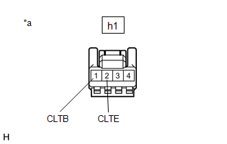
(a) Disconnect the h1 automatic light control sensor connector. |
|
(b) Measure the voltage and resistance according to the value(s) in the table below.
Standard Voltage:
|
Tester Connection |
Condition |
Specified Condition |
|---|---|---|
|
*1: for HV Model
*2: for Gasoline Model |
||
|
h1-1 (CLTB) - h1-2 (CLTE) |
Power switch off*1 |
Below 1 V |
|
Engine switch off*2 |
||
|
Power switch on (IG)*1 |
11 to 14 V |
|
|
Engine switch on (IG)*2 |
||
Standard Resistance:
|
Tester Connection |
Condition |
Specified Condition |
|---|---|---|
|
h1-2 (CLTE) - Body ground |
Always |
Below 1 Ω |
If the result is not as specified, there may be a malfunction on the wire harness side.
(c) Connect the h1 automatic light control sensor connector.
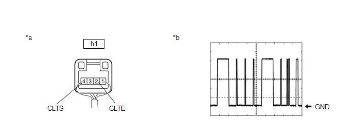
(d) Connect an oscilloscope to terminals h1-2 (CLTE) and h1-4 (CLTS) of the automatic light control sensor connector and check the waveform.

|
*a |
Component with harness connected (Automatic Light Control Sensor) |
*b |
Waveform |
OK:
|
Tester Connection |
Condition |
Tool Setting |
Specified Condition |
|---|---|---|---|
|
*1: for HV Model
*2: for Gasoline Model |
|||
|
h1-2 (CLTE) - h1-4 (CLTS) |
Power switch on (IG)*1 |
2 V/DIV., 10 ms./DIV. |
Pulse generation (See waveform) |
|
Engine switch on (IG)*2 |
|||
HINT:
The communication waveform changes according to the surrounding brightness.
If the result is not as specified, the automatic light control sensor may be malfunctioning.
2. INSPECT COOLER (SOLAR SENSOR) THERMISTOR (w/o Automatic Light Control)
(a) Check the wire harness.
(1) Disconnect the m5 cooler (solar sensor) thermistor connector.
(2) Disconnect the I48 air conditioning amplifier assembly connector.
(3) Measure the resistance according to the value(s) in the table below.
Standard Resistance:
|
Tester Connection |
Condition |
Specified Condition |
|---|---|---|
|
m5-1 - I48-2 (S5-1) |
Always |
Below 1 Ω |
|
M5-2 - I48-9 (TS) |
Always |
Below 1 Ω |
|
m5-1 - Body ground |
Always |
10 kΩ or higher |
|
m5-2 - Body ground |
Always |
10 kΩ or higher |
- If the resistance is not as specified, repair the wire harness.
(4) Reconnect the I48 air conditioning amplifier assembly connector.
(5) Turn the power switch on (IG).
(6) Measure the voltage according to the value(s) in the table below.
Standard Voltage:
|
Tester Connection |
Condition |
Specified Condition |
|---|---|---|
|
m5-1 - m5-2 |
Power switch off |
Below 1 V |
|
m5-1 - m5-2 |
Power switch on (IG) |
4.5 to 5.5 V |
- If the voltage is not as specified, replace the air conditioning amplifier assembly.
(b) Check the cooler (solar sensor) thermistor.
(1) Reconnect the m5 cooler (solar sensor) thermistor connector.
(2) Turn the power switch on (IG).
|
(3) Measure the voltage according to the value(s) in the table below. Standard Voltage:
NOTICE:
HINT:
|
|
|
|
|

