Last Modified: 05-13-2024 6.11:8.1.0 Doc ID: RM100000001GW0N
Model Year Start: 2020 Model: GR Corolla Prod Date Range: [01/2019 - 09/2022]
Title: POWER DISTRIBUTION: INTEGRATION RELAY: INSPECTION; 2020 - 2022 MY Corolla Corolla Hatchback Corolla HV GR Corolla [01/2019 - 09/2022]

INSPECTION

PROCEDURE

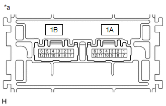
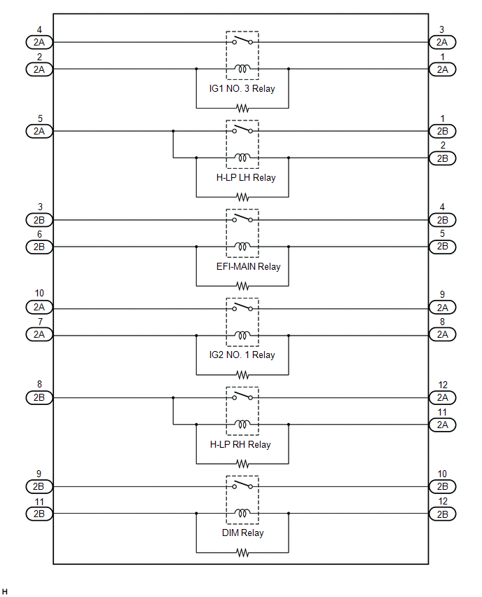
1. INSPECT NO. 1 INTEGRATION RELAY (for Gasoline Model)

(a) IG1 NO. 3 RELAY:

(1) Measure the resistance according to the value(s) in the table below.

Standard Resistance:

Tester Connection

Condition

Specified Condition

1A-4 - 1A-3

Auxiliary battery voltage not applied between terminals 1A-1 and 1A-2

10 kΩ or higher

1A-4 - 1A-3

Auxiliary battery positive (+) → 1A-2

Auxiliary battery negative (-) → 1A-1

Below 1 Ω

If the result is not as specified, replace the No. 1 integration relay.

*a

Component without harness connected

(No. 1 Integration Relay)

(b) H-LP LH RELAY:

(1) Measure the resistance according to the value(s) in the table below.

Standard Resistance:

Tester Connection

Condition

Specified Condition

1A-5 - 1B-1

Auxiliary battery voltage not applied between terminals 1A-5 and 1B-2

10 kΩ or higher

1A-5 - 1B-1

Auxiliary battery positive (+) → 1A-5

Auxiliary battery negative (-) → 1B-2

Below 1 Ω

If the result is not as specified, replace the No. 1 integration relay.

*a

Component without harness connected

(No. 1 Integration Relay)

(c) EFI-MAIN RELAY:

(1) Measure the resistance according to the value(s) in the table below.

Standard Resistance:

Tester Connection

Condition

Specified Condition

1B-3 - 1B-4

Auxiliary battery voltage not applied between terminals 1B-6 and 1B-5

10 kΩ or higher

1B-3 - 1B-4

Auxiliary battery positive (+) → 1B-5

Auxiliary battery negative (-) → 1B-6

Below 1 Ω

If the result is not as specified, replace the No. 1 integration relay.

*a

Component without harness connected

(No. 1 Integration Relay)

(d) IG2 NO. 1 RELAY:

(1) Measure the resistance according to the value(s) in the table below.

Standard Resistance:

Tester Connection

Condition

Specified Condition

1A-10 - 1A-9

Auxiliary battery voltage not applied between terminals 1A-7 and 1A-8

10 kΩ or higher

1A-10 - 1A-9

Auxiliary battery positive (+) → 1A-7

Auxiliary battery negative (-) → 1A-8

Below 1 Ω

If the result is not as specified, replace the No. 1 integration relay.

*a

Component without harness connected

(No. 1 Integration Relay)

(e) H-LP RH RELAY:

(1) Measure the resistance according to the value(s) in the table below.

Standard Resistance:

Tester Connection

Condition

Specified Condition

1B-8 - 1A-12

Auxiliary battery voltage not applied between terminals 1B-8 and 1A-11

10 kΩ or higher

1B-8 - 1A-12

Auxiliary battery positive (+) → 1B-8

Auxiliary battery negative (-) → 1A-11

Below 1 Ω

If the result is not as specified, replace the No. 1 integration relay.

*a

Component without harness connected

(No. 1 Integration Relay)

(f) DIM RELAY:

(1) Measure the resistance according to the value(s) in the table below.

Standard Resistance:

Tester Connection

Condition

Specified Condition

1B-9 - 1B-10

Auxiliary battery voltage not applied between terminals 1B-11 and 1B-12

10 kΩ or higher

1B-9 - 1B-10

Auxiliary battery positive (+) → 1B-11

Auxiliary battery negative (-) → 1B-12

Below 1 Ω

If the result is not as specified, replace the No. 1 integration relay.

*a

Component without harness connected

(No. 1 Integration Relay)

2. INSPECT NO. 1 INTEGRATION RELAY (for HV Model)

(a) IG1 NO. 3 RELAY:

(1) Measure the resistance according to the value(s) in the table below.

Standard Resistance:

Tester Connection

Condition

Specified Condition

2A-4 - 2A-3

Auxiliary battery voltage not applied between terminals 2A-1 and 2A-2

10 kΩ or higher

2A-4 - 2A-3

Auxiliary battery positive (+) → 2A-2

Auxiliary battery negative (-) → 2A-1

Below 1 Ω

If the result is not as specified, replace the No. 1 integration relay.

*a

Component without harness connected

(No. 1 Integration Relay)

(b) H-LP LH RELAY:

(1) Measure the resistance according to the value(s) in the table below.

Standard Resistance:

Tester Connection

Condition

Specified Condition

2A-5 - 2B-1

Auxiliary battery voltage not applied between terminals 2A-5 and 2B-2

10 kΩ or higher

2A-5 - 2B-1

Auxiliary battery positive (+) → 2A-5

Auxiliary battery negative (-) → 2B-2

Below 1 Ω

If the result is not as specified, replace the No. 1 integration relay.

*a

Component without harness connected

(No. 1 Integration Relay)

(c) EFI-MAIN RELAY:

(1) Measure the resistance according to the value(s) in the table below.

Standard Resistance:

Tester Connection

Condition

Specified Condition

2B-3 - 2B-4

Auxiliary battery voltage not applied between terminals 2B-6 and 2B-5

10 kΩ or higher

2B-3 - 2B-4

Auxiliary battery positive (+) → 2B-6

Auxiliary battery negative (-) → 2B-5

Below 1 Ω

If the result is not as specified, replace the No. 1 integration relay.

*a

Component without harness connected

(No. 1 Integration Relay)

(d) IG2 NO. 1 RELAY:

(1) Measure the resistance according to the value(s) in the table below.

Standard Resistance:

Tester Connection

Condition

Specified Condition

2A-10 - 2A-9

Auxiliary battery voltage not applied between terminals 2A-7 and 2A-8

10 kΩ or higher

2A-10 - 2A-9

Auxiliary battery positive (+) → 2A-7

Auxiliary battery negative (-) → 2A-8

Below 1 Ω

If the result is not as specified, replace the No. 1 integration relay.

*a

Component without harness connected

(No. 1 Integration Relay)

(e) H-LP RH RELAY:

(1) Measure the resistance according to the value(s) in the table below.

Standard Resistance:

Tester Connection

Condition

Specified Condition

2B-8 - 2A-12

Auxiliary battery voltage not applied between terminals 2B-8 and 2A-11

10 kΩ or higher

2B-8 - 2A-12

Auxiliary battery positive (+) → 2B-8

Auxiliary battery negative (-) → 2A-11

Below 1 Ω

If the result is not as specified, replace the No. 1 integration relay.

*a

Component without harness connected

(No. 1 Integration Relay)

(f) DIM RELAY:

(1) Measure the resistance according to the value(s) in the table below.

Standard Resistance:

Tester Connection

Condition

Specified Condition

2B-9 - 2B-10

Auxiliary battery voltage not applied between terminals 2B-11 and 2B-12

10 kΩ or higher

2B-9 - 2B-10

Auxiliary battery positive (+) → 2B-11

Auxiliary battery negative (-) → 2B-12

Below 1 Ω

If the result is not as specified, replace the No. 1 integration relay.

*a

Component without harness connected

(No. 1 Integration Relay)