| Last Modified: 05-13-2024 | 6.11:8.1.0 | Doc ID: RM100000001GTFK |
| Model Year Start: 2020 | Model: GR Corolla | Prod Date Range: [01/2019 - 09/2022] |
| Title: AUDIO / VIDEO: AUDIO AND VISUAL SYSTEM (for Gasoline Model with Dual Knob Type): B1324,B1325; Lost Communication with Meter; 2020 - 2022 MY Corolla Corolla Hatchback GR Corolla [01/2019 - 09/2022] | ||
|
DTC |
B1324 |
Lost Communication with Meter |
|
DTC |
B1325 |
Lost Communication with HUD |
DESCRIPTION
These DTCs are stored when communication between the radio and display receiver assembly and combination meter assembly or headup display (meter mirror sub-assembly)* is not possible.
|
DTC No. |
Detection Item |
DTC Detection Condition |
Trouble Area |
|---|---|---|---|
|
B1324 |
Lost Communication with Meter |
CAN reception error |
|
|
B1325 |
Lost Communication with HUD |
CAN reception error |
|
- *: w/ Headup Display System
HINT:
The radio and display receiver assembly is the master unit.
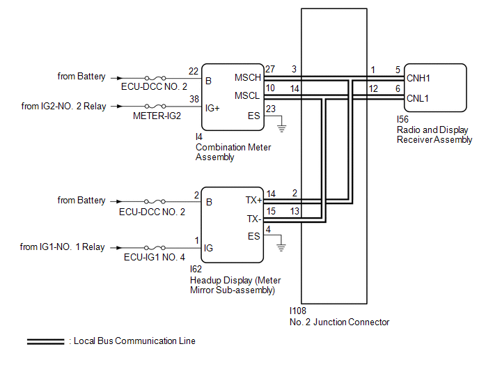
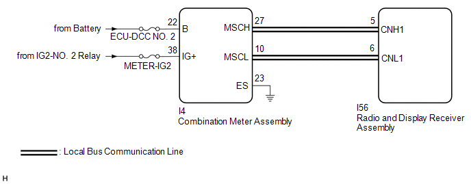
WIRING DIAGRAM
w/ Headup Display System
w/o Headup Display System
CAUTION / NOTICE / HINT
NOTICE:
- Depending on the parts that are replaced during vehicle inspection or maintenance, performing initialization, registration or calibration may be needed. Refer to Precaution for Audio and Visual System.
-
When replacing the radio and display receiver assembly, always replace it with a new one. If a radio and display receiver assembly which was installed to another vehicle is used, the following may occur:
- A communication malfunction DTC may be stored.
- The radio and display receiver assembly may not operate normally.
- Inspect the fuses for circuits related to this system before performing the following procedure.
PROCEDURE
|
1. |
CHECK DTC |
(a) Check for DTCs and check that no DTCs are output.
Body Electrical > Navigation System > Trouble Codes
|
Result |
Proceed to |
|---|---|
|
DTC B1324 and B1325 are not output |
A |
|
DTC B1324 and B1325 are output |
B |
|
DTC B1324 is output |
C |
|
DTC B1325 is output |
D |
| A |

|
| C |
|
| D |
|
|

|
2. |
CHECK LOCAL BUS |
(a) Disconnect the cable from the negative (-) battery terminal.
(b) Measure the resistance according to the value(s) in the table below.
Standard Resistance:
|
Tester Connection |
Condition |
Specified Condition |
|---|---|---|
|
I108-1 - I108-12 |
Cable disconnected from negative (-) battery terminal |
54 to 69 Ω |
|
Result |
Proceed to |
|---|---|
|
OK |
A |
|
NG (Below 54 Ω) |
B |
|
NG (70 Ω or higher) |
C |
| A |
|
| C |
|
|
|
3. |
CHECK HARNESS AND CONNECTOR (RADIO AND DISPLAY RECEIVER ASSEMBLY - NO. 2 JUNCTION CONNECTOR) |
(a) Disconnect the cable from the negative (-) battery terminal.
(b) Disconnect the I108 No. 2 junction connector.
(c) Measure the resistance according to the value(s) in the table below.
Standard Resistance:
|
Tester Connection |
Condition |
Specified Condition |
|---|---|---|
|
I108-1 - I108-12 |
Cable disconnected from negative (-) battery terminal |
108 to 132 Ω |
| NG |
|
|
|
4. |
CHECK HARNESS AND CONNECTOR (COMBINATION METER ASSEMBLY - NO. 2 JUNCTION CONNECTOR) |
(a) Disconnect the cable from the negative (-) battery terminal.
(b) Disconnect the I108 No. 2 junction connector.
(c) Measure the resistance according to the value(s) in the table below.
Standard Resistance:
|
Tester Connection |
Condition |
Specified Condition |
|---|---|---|
|
I108-3 - I108-14 |
Cable disconnected from negative (-) battery terminal |
108 to 132 Ω |
| NG |
|
|
|
5. |
CHECK HARNESS AND CONNECTOR (HEADUP DISPLAY (METER MIRROR SUB-ASSEMBLY) - NO. 2 JUNCTION CONNECTOR) |
(a) Disconnect the cable from the negative (-) battery terminal.
(b) Disconnect the I108 No. 2 junction connector.
(c) Measure the resistance according to the value(s) in the table below.
Standard Resistance:
|
Tester Connection |
Condition |
Specified Condition |
|---|---|---|
|
I108-2 - I108-13 |
Cable disconnected from negative (-) battery terminal |
200 Ω or higher |
| OK |
|
REPLACE NO. 2 JUNCTION CONNECTOR |
|
|
6. |
CHECK HARNESS AND CONNECTOR (HEADUP DISPLAY (METER MIRROR SUB-ASSEMBLY) - NO. 2 JUNCTION CONNECTOR) |
(a) Disconnect the cable from the negative (-) battery terminal.
(b) Disconnect the I62 headup display (meter mirror sub-assembly) connector.
(c) Connect the I108 No. 2 junction connector.
(d) Measure the resistance according to the value(s) in the table below.
Standard Resistance:
|
Tester Connection |
Condition |
Specified Condition |
|---|---|---|
|
I62-14 (TX+) - I62-15 (TX-) |
Cable disconnected from negative (-) battery terminal |
54 to 69 Ω |
| OK |
|
REPLACE HEADUP DISPLAY (METER MIRROR SUB-ASSEMBLY)
|
![2020 MY Corolla Corolla Hatchback Corolla HV GR Corolla [01/2019 - 03/2019]; METER / GAUGE / DISPLAY: HEADUP DISPLAY: REMOVAL](/t3Portal/stylegraphics/info.gif)
| NG |
|
REPAIR OR REPLACE HARNESS OR CONNECTOR |
|
7. |
CHECK HARNESS AND CONNECTOR (COMBINATION METER ASSEMBLY - NO. 2 JUNCTION CONNECTOR) |
(a) Disconnect the cable from the negative (-) battery terminal.
(b) Disconnect the I4 combination meter assembly connector.
(c) Connect the I108 No. 2 junction connector.
(d) Measure the resistance according to the value(s) in the table below.
Standard Resistance:
|
Tester Connection |
Condition |
Specified Condition |
|---|---|---|
|
I4-27 (MSCH) - I4-10 (MSCL) |
Cable disconnected from negative (-) battery terminal |
108 to 132 Ω |
| OK |
|
REPLACE COMBINATION METER ASSEMBLY
|
| NG |
|
REPAIR OR REPLACE HARNESS OR CONNECTOR |
|
8. |
CHECK HARNESS AND CONNECTOR (RADIO AND DISPLAY RECEIVER ASSEMBLY - NO. 2 JUNCTION CONNECTOR) |
(a) Disconnect the cable from the negative (-) battery terminal.
(b) Disconnect the I56 radio and display receiver assembly connector.
(c) Connect the I108 No. 2 junction connector.
(d) Measure the resistance according to the value(s) in the table below.
Standard Resistance:
|
Tester Connection |
Condition |
Specified Condition |
|---|---|---|
|
I56-5 (CNH1) - I56-6 (CNL1) |
Cable disconnected from negative (-) battery terminal |
108 to 132 Ω |
| OK |
|
REPLACE RADIO AND DISPLAY RECEIVER ASSEMBLY
|
| NG |
|
REPAIR OR REPLACE HARNESS OR CONNECTOR |
|
9. |
CHECK HARNESS AND CONNECTOR (RADIO AND DISPLAY RECEIVER ASSEMBLY - NO. 2 JUNCTION CONNECTOR) |
(a) Disconnect the cable from the negative (-) battery terminal.
(b) Disconnect the I56 radio and display receiver assembly connector.
(c) Measure the resistance according to the value(s) in the table below.
Standard Resistance:
|
Tester Connection |
Condition |
Specified Condition |
|---|---|---|
|
I56-5 (CNH1) - I56-6 (CNL1) |
Cable disconnected from negative (-) battery terminal |
108 to 132 Ω |
| OK |
|
REPLACE RADIO AND DISPLAY RECEIVER ASSEMBLY
|
|
|
10. |
CHECK HARNESS AND CONNECTOR (RADIO AND DISPLAY RECEIVER ASSEMBLY - NO. 2 JUNCTION CONNECTOR) |
(a) Disconnect the cable from the negative (-) battery terminal.
(b) Disconnect the I108 No. 2 junction connector.
(c) Connect the I56 radio and display receiver assembly connector.
(d) Measure the resistance according to the value(s) in the table below.
Standard Resistance:
|
Tester Connection |
Condition |
Specified Condition |
|---|---|---|
|
I108-1 - I108-12 |
Cable disconnected from negative (-) battery terminal |
108 to 132 Ω |
| OK |
|
REPLACE NO. 2 JUNCTION CONNECTOR |
| NG |
|
REPAIR OR REPLACE HARNESS OR CONNECTOR |
|
11. |
CHECK HARNESS AND CONNECTOR (COMBINATION METER ASSEMBLY POWER SOURCE) |
(a) Disconnect the I4 combination meter assembly connector.
(b) Measure the resistance according to the value(s) in the table below.
Standard Resistance:
|
Tester Connection |
Condition |
Specified Condition |
|---|---|---|
|
I4-23 (ES) - Body ground |
Always |
Below 1 Ω |
(c) Measure the voltage according to the value(s) in the table below.
Standard Voltage:
|
Tester Connection |
Condition |
Specified Condition |
|---|---|---|
|
I4-22 (B) - Body ground |
Always |
11 to 14 V |
|
I4-38 (IG+) - Body ground |
Ignition switch ON |
11 to 14 V |
|
Result |
Proceed to |
|---|---|
|
OK (w/ Headup Display System) |
A |
|
OK (w/o Headup Display System) |
B |
|
NG |
C |
| B |
|
| C |
|
REPAIR OR REPLACE HARNESS OR CONNECTOR |
|
|
12. |
CHECK HARNESS AND CONNECTOR (COMBINATION METER ASSEMBLY - NO. 2 JUNCTION CONNECTOR) |
(a) Disconnect the cable from the negative (-) battery terminal.
(b) Disconnect the I108 No. 2 junction connector.
(c) Connect the I4 combination meter assembly connector.
(d) Measure the resistance according to the value(s) in the table below.
Standard Resistance:
|
Tester Connection |
Condition |
Specified Condition |
|---|---|---|
|
I108-3 - I108-14 |
Cable disconnected from negative (-) battery terminal |
108 to 132 Ω |
| NG |
|
|
|
13. |
CHECK HARNESS AND CONNECTOR (RADIO AND DISPLAY RECEIVER ASSEMBLY - NO. 2 JUNCTION CONNECTOR) |
(a) Disconnect the cable from the negative (-) battery terminal.
(b) Disconnect the I108 No. 2 junction connector.
(c) Measure the resistance according to the value(s) in the table below.
Standard Resistance:
|
Tester Connection |
Condition |
Specified Condition |
|---|---|---|
|
I108-1 - I108-12 |
Cable disconnected from negative (-) battery terminal |
108 to 132 Ω |
| OK |
|
REPLACE NO. 2 JUNCTION CONNECTOR |
|
|
14. |
CHECK HARNESS AND CONNECTOR (RADIO AND DISPLAY RECEIVER ASSEMBLY - NO. 2 JUNCTION CONNECTOR) |
(a) Disconnect the cable from the negative (-) battery terminal.
(b) Disconnect the I56 radio and display receiver assembly connector.
(c) Connect the I108 No. 2 junction connector.
(d) Measure the resistance according to the value(s) in the table below.
Standard Resistance:
|
Tester Connection |
Condition |
Specified Condition |
|---|---|---|
|
I56-5 (CNH1) - I56-6 (CNL1) |
Cable disconnected from negative (-) battery terminal |
108 to 132 Ω |
| OK |
|
REPLACE RADIO AND DISPLAY RECEIVER ASSEMBLY
|
| NG |
|
REPAIR OR REPLACE HARNESS OR CONNECTOR |
|
15. |
CHECK HARNESS AND CONNECTOR (COMBINATION METER ASSEMBLY - NO. 2 JUNCTION CONNECTOR) |
(a) Disconnect the cable from the negative (-) battery terminal.
(b) Disconnect the I4 combination meter assembly connector.
(c) Connect the I108 No. 2 junction connector.
(d) Measure the resistance according to the value(s) in the table below.
Standard Resistance:
|
Tester Connection |
Condition |
Specified Condition |
|---|---|---|
|
I4-27 (MSCH) - I4-10 (MSCL) |
Cable disconnected from negative (-) battery terminal |
108 to 132 Ω |
| OK |
|
REPLACE COMBINATION METER ASSEMBLY
|
| NG |
|
REPAIR OR REPLACE HARNESS OR CONNECTOR |
|
16. |
CHECK HARNESS AND CONNECTOR |
(a) Disconnect the cable from the negative (-) battery terminal.
(b) Disconnect the I4 combination meter assembly connector.
(c) Measure the resistance according to the value(s) in the table below.
Standard Resistance:
|
Tester Connection |
Condition |
Specified Condition |
|---|---|---|
|
I4-27 (MSCH) - I4-10 (MSCL) |
Cable disconnected from negative (-) battery terminal |
108 to 132 Ω |
| OK |
|
REPLACE COMBINATION METER ASSEMBLY
|
|
|
17. |
CHECK HARNESS AND CONNECTOR (RADIO AND DISPLAY RECEIVER ASSEMBLY - COMBINATION METER ASSEMBLY) |
(a) Disconnect the I56 radio and display receiver assembly connector.
(b) Disconnect the I4 combination meter assembly connector.
(c) Measure the resistance according to the value(s) in the table below.
Standard Resistance:
|
Tester Connection |
Condition |
Specified Condition |
|---|---|---|
|
I56-5 (CNH1) - I4-27 (MSCH) |
Always |
Below 1 Ω |
|
I56-6 (CNL1) - I4-10 (MSCL) |
Always |
Below 1 Ω |
|
I56-5 (CNH1) or I4-27 (MSCH) - Body ground |
Always |
10 kΩ or higher |
|
I56-6 (CNL1) or I4-10 (MSCL) - Body ground |
Always |
10 kΩ or higher |
| OK |
|
REPLACE RADIO AND DISPLAY RECEIVER ASSEMBLY
|
| NG |
|
REPAIR OR REPLACE HARNESS OR CONNECTOR |
|
18. |
CHECK HARNESS AND CONNECTOR (HEADUP DISPLAY (METER MIRROR SUB-ASSEMBLY) POWER SOURCE) |
(a) Disconnect the I62 headup display (meter mirror sub-assembly) connector.
(b) Measure the resistance according to the value(s) in the table below.
Standard Resistance:
|
Tester Connection |
Condition |
Specified Condition |
|---|---|---|
|
I62-4 (ES) - Body ground |
Always |
Below 1 Ω |
(c) Measure the voltage according to the value(s) in the table below.
Standard Voltage:
|
Tester Connection |
Condition |
Specified Condition |
|---|---|---|
|
I62-2 (B) - Body ground |
Always |
11 to 14 V |
|
I62-1 (IG) - Body ground |
Ignition switch ON |
11 to 14 V |
| NG |
|
REPAIR OR REPLACE HARNESS OR CONNECTOR |
|
|
19. |
CHECK HARNESS AND CONNECTOR (HEADUP DISPLAY (METER MIRROR SUB-ASSEMBLY) - NO. 2 JUNCTION CONNECTOR) |
(a) Disconnect the cable from the negative (-) battery terminal.
(b) Disconnect the I108 No. 2 junction connector.
(c) Connect the I62 headup display (meter mirror sub-assembly) connector.
(d) Measure the resistance according to the value(s) in the table below.
Standard Resistance:
|
Tester Connection |
Condition |
Specified Condition |
|---|---|---|
|
I108-2 - I108-13 |
Cable disconnected from negative (-) battery terminal |
200 Ω or higher |
| NG |
|
|
|
20. |
CHECK HARNESS AND CONNECTOR (RADIO AND DISPLAY RECEIVER ASSEMBLY - NO. 2 JUNCTION CONNECTOR) |
(a) Disconnect the cable from the negative (-) battery terminal.
(b) Disconnect the I108 No. 2 junction connector.
(c) Measure the resistance according to the value(s) in the table below.
Standard Resistance:
|
Tester Connection |
Condition |
Specified Condition |
|---|---|---|
|
I108-1 - I108-12 |
Cable disconnected from negative (-) battery terminal |
108 to 132 Ω |
| OK |
|
REPLACE NO. 2 JUNCTION CONNECTOR |
|
|
21. |
CHECK HARNESS AND CONNECTOR (RADIO AND DISPLAY RECEIVER ASSEMBLY - NO. 2 JUNCTION CONNECTOR) |
(a) Disconnect the cable from the negative (-) battery terminal.
(b) Disconnect the I56 radio and display receiver assembly connector.
(c) Connect the I108 No. 2 junction connector.
(d) Measure the resistance according to the value(s) in the table below.
Standard Resistance:
|
Tester Connection |
Condition |
Specified Condition |
|---|---|---|
|
I56-5 (CNH1) - I56-6 (CNL1) |
Cable disconnected from negative (-) battery terminal |
108 to 132 Ω |
| OK |
|
REPLACE RADIO AND DISPLAY RECEIVER ASSEMBLY
|
| NG |
|
REPAIR OR REPLACE HARNESS OR CONNECTOR |
|
22. |
CHECK HARNESS AND CONNECTOR (HEADUP DISPLAY (METER MIRROR SUB-ASSEMBLY) - NO. 2 JUNCTION CONNECTOR) |
(a) Disconnect the cable from the negative (-) battery terminal.
(b) Disconnect the I62 headup display (meter mirror sub-assembly) connector.
(c) Connect the I108 No. 2 junction connector.
(d) Measure the resistance according to the value(s) in the table below.
Standard Resistance:
|
Tester Connection |
Condition |
Specified Condition |
|---|---|---|
|
I62-14 (TX+) - I62-15 (TX-) |
Cable disconnected from negative (-) battery terminal |
54 to 69 Ω |
| OK |
|
REPLACE HEADUP DISPLAY (METER MIRROR SUB-ASSEMBLY)
|
| NG |
|
REPAIR OR REPLACE HARNESS OR CONNECTOR |
|
|
|