- Clear the data stored during previous linear solenoid valve offset learning, ABS holding solenoid valve learning, brake pedal stroke sensor assembly zero point calibration and system information memorization
- Perform linear solenoid valve offset learning, ABS holding solenoid valve learning, brake pedal stroke sensor assembly zero point calibration and system information memorization
| Last Modified: 05-13-2024 | 6.11:8.1.0 | Doc ID: RM100000001GOQH |
| Model Year Start: 2020 | Model: Corolla | Prod Date Range: [01/2019 - 09/2022] |
| Title: BRAKE SYSTEM (OTHER): BRAKE PEDAL (for HV Model): REMOVAL; 2020 - 2022 MY Corolla Corolla HV [01/2019 - 09/2022] | ||
REMOVAL
CAUTION / NOTICE / HINT
The necessary procedures (adjustment, calibration, initialization, or registration) that must be performed after parts are removed, installed, or replaced during brake pedal support assembly removal/installation are shown below.
Necessary Procedures After Parts Removed/Installed/Replaced
|
Replaced Part or Performed Procedure |
Necessary Procedure |
Effect/Inoperative Function when Necessary Procedure not Performed |
Link |
|---|---|---|---|
|
Auxiliary battery terminal is disconnected/reconnected |
Perform steering sensor zero point calibration |
Lane Control System |
|
|
Pre-collision System |
|||
|
Removal/installation/replacement of brake pedal support assembly |
|
|
NOTICE:
After the power switch is turned off, the radio and display receiver assembly records various types of memory and settings. As a result, after turning the power switch off, make sure to wait at least 85 seconds before disconnecting the cable from the negative (-) auxiliary battery terminal. (for Audio and Visual System)
CAUTION / NOTICE / HINT
NOTICE:
While the auxiliary battery is connected, even if the power switch is off, the brake control system activates when the brake pedal is depressed or any door courtesy switch turns on. Therefore, when servicing the brake system components, do not operate the brake pedal or open/close the doors while the auxiliary battery is connected.
PROCEDURE
1. REMOVE LOWER NO. 1 INSTRUMENT PANEL AIRBAG ASSEMBLY
2. REMOVE FRONT NO. 1 CONSOLE BOX INSERT
3. REMOVE NO. 1 AIR DUCT
4. REMOVE BRAKE PEDAL STROKE SENSOR ASSEMBLY
5. REMOVE STOP LIGHT SWITCH ASSEMBLY
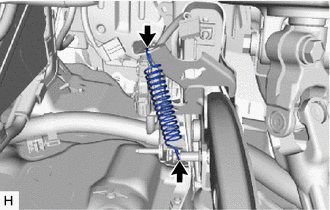
6. REMOVE BRAKE PEDAL RETURN SPRING
|
(a) Remove the brake pedal return spring from the brake pedal support assembly and push rod pin. |
|
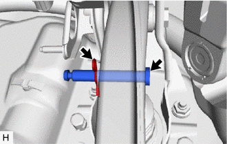
7. REMOVE PUSH ROD PIN
|
(a) Remove the clip and push rod pin to separate the brake pedal support assembly from the brake master cylinder push rod clevis. |
|
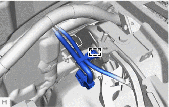
8. REMOVE BRAKE PEDAL SUPPORT ASSEMBLY
|
(a) Disengage the clamp to separate the wire harness from the brake pedal support assembly. |
|
|
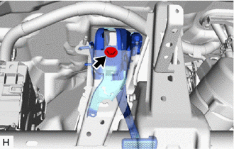
(b) Remove the bolt and separate the brake pedal support assembly from the instrument panel reinforcement assembly. |
|
(c) Remove the 2 clips.
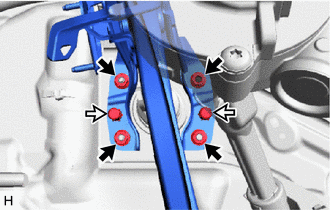

|
Nut |

|
Clip |
(d) Remove the 4 nuts and brake pedal support assembly.
|
(e) Remove the nut from the brake pedal support assembly. |
|
9. REMOVE STOP LIGHT SWITCH MOUNTING ADJUSTER
|
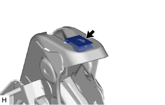
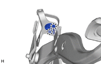
(a) Disengage the 2 claws and remove the stop light switch mounting adjuster. |
|
10. REMOVE BRAKE PEDAL PAD
(a) Remove the brake pedal pad from the brake pedal support assembly.
|
|
|
![2020 - 2022 MY Corolla Corolla HV [01/2019 - 09/2022]; PRE-COLLISION: PRE-COLLISION SYSTEM (for HV Model): INITIALIZATION](/t3Portal/stylegraphics/info.gif)
