- Bleed air
- Clear the data stored during previous linear solenoid valve offset learning, ABS holding solenoid valve learning, brake pedal stroke sensor assembly zero point calibration and system information memorization
- Perform linear solenoid valve offset learning, ABS holding solenoid valve learning, brake pedal stroke sensor assembly zero point calibration and system information memorization
| Last Modified: 05-13-2024 | 6.11:8.1.0 | Doc ID: RM100000001GOOR |
| Model Year Start: 2020 | Model: Corolla | Prod Date Range: [01/2019 - 09/2022] |
| Title: BRAKE CONTROL / DYNAMIC CONTROL SYSTEMS: BRAKE ACTUATOR (for HV Model): REMOVAL; 2020 - 2022 MY Corolla Corolla HV [01/2019 - 09/2022] | ||
REMOVAL
CAUTION / NOTICE / HINT
The necessary procedures (adjustment, calibration, initialization, or registration) that must be performed after parts are removed, installed, or replaced during brake actuator assembly removal/installation are shown below.
Necessary Procedures After Parts Removed/Installed/Replaced
|
Replaced Part or Performed Procedure |
Necessary Procedure |
Effect/Inoperative Function when Necessary Procedure not Performed |
Link |
|---|---|---|---|
|
Auxiliary battery terminal is disconnected/reconnected |
Perform steering sensor zero point calibration |
Lane Control System |
|
|
Pre-collision System |
|||
|
Replacement of brake actuator assembly |
|
|
for Initialization:
for Calibration:
|
|
Operate the electric parking brake switch (electric parking brake switch assembly) |
Parking brake indicator light (red) blinks when the power switch is first turned on (IG) |
|
NOTICE:
After the power switch is turned off, the radio and display receiver assembly records various types of memory and settings. As a result, after turning the power switch off, make sure to wait at least 85 seconds before disconnecting the cable from the negative (-) auxiliary battery terminal. (for Audio and Visual System)
CAUTION / NOTICE / HINT
NOTICE:
While the auxiliary battery is connected, even if the power switch is off, the brake control system activates when the brake pedal is depressed or any door courtesy switch turns on. Therefore, when servicing the brake system components, do not operate the brake pedal or open/close the doors while the auxiliary battery is connected.
PROCEDURE
1. PRECAUTION
NOTICE:
After turning the power switch off, waiting time may be required before disconnecting the cable from the negative (-) auxiliary battery terminal. Therefore, make sure to read the disconnecting the cable from the negative (-) auxiliary battery terminal notices before proceeding with work.
2. RECOVER REFRIGERANT FROM REFRIGERATION SYSTEM
for HFC-134a(R134a): Click here
![2020 - 2025 MY Corolla Corolla Hatchback Corolla HV GR Corolla [01/2019 - ]; HEATING / AIR CONDITIONING: REFRIGERANT (for HFC-134a(R134a)): REPLACEMENT+](/t3Portal/stylegraphics/info.gif)
for HFO-1234yf(R1234yf): Click here
3. REMOVE WINDSHIELD WIPER MOTOR AND LINK ASSEMBLY
Click here
4. REMOVE NO. 1 HEATER AIR DUCT SPLASH SHIELD SEAL
Click here
5. REMOVE OUTER COWL TOP PANEL SUB-ASSEMBLY
Click here
6. PERFORM ACCUMULATOR PRESSURE ZERO DOWN
Click here
7. DRAIN BRAKE FLUID
NOTICE:
If brake fluid leaks onto any painted surface, immediately wash it off.
8. REMOVE SECURITY HORN ASSEMBLY
Click here
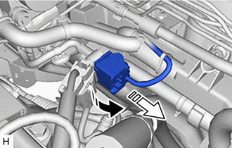
9. REMOVE SUCTION PIPE SUB-ASSEMBLY
(a) Remove the bolt and rotate the hook connector as shown in the illustration.
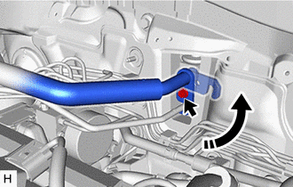

|
Rotate in this Direction |
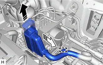
(b) Disconnect the suction pipe sub-assembly from the air conditioning unit assembly.
|
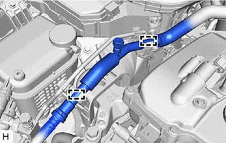
(c) Disengage the 2 clamps to separate the suction pipe sub-assembly. |
|
(d) Remove the O-ring from the suction pipe sub-assembly.
NOTICE:
Seal the openings of the disconnected parts using vinyl tape to prevent entry of moisture and foreign matter.
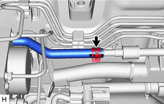
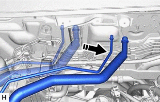
10. REMOVE AIR CONDITIONING TUBE & ACCESSORY ASSEMBLY
(a) Disconnect the air conditioner tube and accessory assembly from the air conditioning unit assembly.
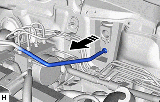
|
|
Remove in this Direction |
|
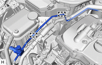
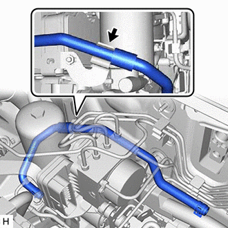
(b) Disengage the 2 clamps to separate the air conditioner tube and accessory assembly. |
|
(c) Remove the O-ring from the air conditioner tube and accessory assembly.
NOTICE:
Seal the openings of the disconnected parts using vinyl tape to prevent entry of moisture and foreign matter.
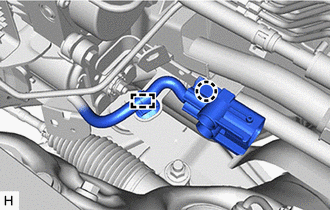
11. DISCONNECT ENGINE ROOM MAIN WIRE
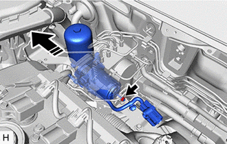
(a) Release the lock lever and disconnect the connector from the brake booster pump assembly as shown in the illustration.
|
|
Release the lock lever |

|
Disconnect the connector |
NOTICE:
Be careful not to allow any brake fluid to enter the connector.
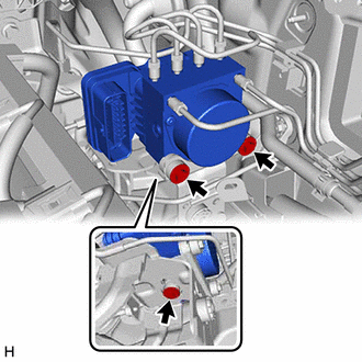
(b) Release the lock lever and disconnect the connector from the brake actuator assembly as shown in the illustration.
|
|
Release the lock lever |
|
|
Disconnect the connector |
NOTICE:
Be careful not to allow any brake fluid to enter the connector.
(c) Disengage the clamp and separate the engine room main wire.
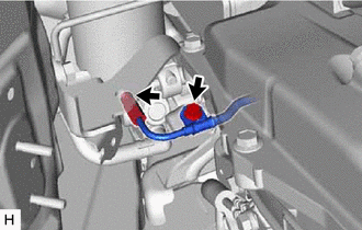
12. SEPARATE NO. 1 BRAKE ACTUATOR HOSE
|
(a) Slide the clip and disconnect the No. 1 brake actuator hose from the No. 1 brake actuator tube. |
|
|
(b) Separate the No. 1 brake actuator hose from the brake actuator hose clamp. |
|
13. SEPARATE BRAKE LINE
|
(a) Use tags or make a memo to identify the places to reconnect the brake lines. |
|
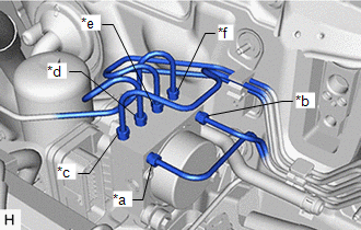
|
(b) Using a union nut wrench, disconnect the 6 brake lines from the brake actuator assembly. |
|
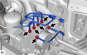
14. SEPARATE ACCUMULATOR TO BRAKE MASTER CYLINDER TUBE
|
(a) Using a union nut wrench, disconnect the accumulator to brake master cylinder tube from the brake booster pump assembly. |
|
(b) Remove the bolt to separate the accumulator to brake master cylinder tube.
15. SEPARATE BRAKE BOOSTER PUMP ASSEMBLY
|
(a) Disengage the claw and clamp to separate the brake booster pump assembly wire harness from the brake actuator bracket assembly. |
|
(b) Remove the nut to separate the brake booster pump assembly from the brake actuator bracket assembly.
|
|
Move in this Direction |
HINT:
Move the brake booster pump assembly to the position where the lower bolt of the brake actuator assembly can be removed.
16. REMOVE BRAKE ACTUATOR ASSEMBLY
(a) Move aside the suction pipe sub-assembly and air conditioner tube and accessory assembly as shown in the illustration.
NOTICE:
Do not apply excessive force to the suction pipe sub-assembly and air conditioner tube and accessory assembly.
|
|
Move in this Direction |
|
(b) Remove the 3 bolts and brake actuator assembly from the brake actuator bracket assembly. NOTICE:
|
|
|
|
|