| Last Modified: 07-31-2024 | 6.11:8.1.0 | Doc ID: RM100000001GKC7 |
| Model Year Start: 2020 | Model: Corolla | Prod Date Range: [01/2019 - 11/2022] |
| Title: 2ZR-FAE (ENGINE CONTROL): SFI SYSTEM: Fuel Pump Control Circuit; 2020 - 2023 MY Corolla [01/2019 - 11/2022] | ||
|
Fuel Pump Control Circuit |
DESCRIPTION
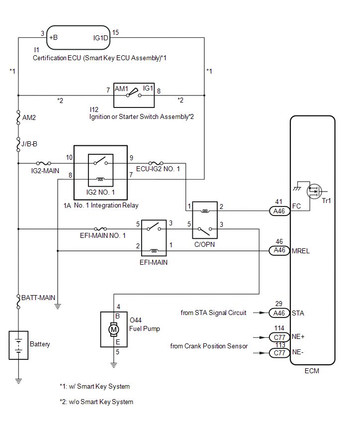
When the engine is cranked, the ST relay drive signal output from the ignition or starter switch assembly*1 or certification ECU (smart key ECU assembly)*2 is input into the STA terminal of the ECM, and the NE signal generated by the crank position sensor is also input into the NE+ terminal. The ECM interprets that the engine is cranked, and turns transistor Tr1 in the ECM internal circuit on. Current flows to the C/OPN relay by turning Tr1 on. Then, the fuel pump operates.
While the NE signal is input into the ECM with the engine running, the ECM turns Tr1 on continuously.
- *1: w/o Smart Key System
- *2: w/ Smart Key System
WIRING DIAGRAM

CAUTION / NOTICE / HINT
NOTICE:
Inspect the fuses for circuits related to this system before performing the following procedure.
PROCEDURE
|
1. |
PERFORM ACTIVE TEST USING TECHSTREAM (CONTROL THE FUEL PUMP/SPEED) |
(a) Connect the Techstream to the DLC3.
(b) Turn the ignition switch to ON.
(c) Turn the Techstream on.
(d) Enter the following menus: Powertrain / Engine and ECT / Active Test / Control the Fuel Pump/Speed.
Powertrain > Engine and ECT > Active Test
|
Tester Display |
|---|
|
Control the Fuel Pump / Speed |
(e) Check whether the fuel pump operating sound occurs when performing the Active Test on the Techstream.
|
Result |
Proceed to |
|---|---|
|
Fuel pump operating sound does not occur |
A |
|
Fuel pump operating sound occurs |
B |
| B |

|
|
|
2. |
CHECK TERMINAL VOLTAGE (POWER SOURCE OF C/OPN RELAY) |
|
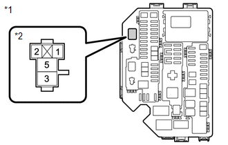
(a) Remove the C/OPN relay from the No. 1 engine room relay block and No. 1 junction block assembly. |
|
(b) Turn the ignition switch to ON.
(c) Measure the voltage according to the value(s) in the table below.
Standard Voltage:
|
Tester Connection |
Condition |
Specified Condition |
|---|---|---|
|
1 (C/OPN relay) - Body ground |
Ignition switch ON |
11 to 14 V |
| NG |

|
|
|
3. |
INSPECT C/OPN RELAY |
(a) Inspect the C/OPN relay.
| NG |

|
REPLACE C/OPN RELAY |
|
|
4. |
CHECK HARNESS AND CONNECTOR (C/OPN RELAY - ECM) |
(a) Remove the C/OPN relay from the No. 1 engine room relay block and No. 1 junction block assembly.
(b) Disconnect the ECM connector.
(c) Measure the resistance according to the value(s) in the table below.
Standard Resistance:
|
Tester Connection |
Condition |
Specified Condition |
|---|---|---|
|
2 (C/OPN relay) - A46-41 (FC) |
Always |
Below 1 Ω |
|
2 (C/OPN relay) or A46-41 (FC) - Body ground and other terminals |
Always |
10 kΩ or higher |
| NG |

|
REPAIR OR REPLACE HARNESS OR CONNECTOR |
|
|
5. |
CHECK HARNESS AND CONNECTOR (C/OPN RELAY - FUEL PUMP) |
(a) Remove the C/OPN relay from the No. 1 engine room relay block and No. 1 junction block assembly.
(b) Disconnect the fuel pump connector.
(c) Measure the resistance according to the value(s) in the table below.
Standard Resistance:
|
Tester Connection |
Condition |
Specified Condition |
|---|---|---|
|
3 (C/OPN relay) - O44-4 (B) |
Always |
Below 1 Ω |
|
3 (C/OPN relay) or O44-4 (B) - Body ground and other terminals |
Always |
10 kΩ or higher |
| NG |

|
REPAIR OR REPLACE HARNESS OR CONNECTOR |
|
|
6. |
CHECK HARNESS AND CONNECTOR (FUEL PUMP - BODY GROUND) |
(a) Disconnect the fuel pump connector.
(b) Measure the resistance according to the value(s) in the table below.
Standard Resistance:
|
Tester Connection |
Condition |
Specified Condition |
|---|---|---|
|
O44-5 (E) - Body ground |
Always |
Below 1 Ω |
| NG |

|
REPAIR OR REPLACE HARNESS OR CONNECTOR |
|
|
7. |
INSPECT FUEL PUMP |
(a) Inspect the fuel pump.
HINT:
Perform "Inspection After Repair" after replacing the fuel pump.
| NG |

|
|
|
8. |
CHECK HARNESS AND CONNECTOR (EFI-MAIN RELAY - C/OPN RELAY) |
(a) Remove the EFI-MAIN relay and C/OPN relay from the No. 1 engine room relay block and No. 1 junction block assembly.
(b) Measure the resistance according to the value(s) in the table below.
Standard Resistance:
|
Tester Connection |
Condition |
Specified Condition |
|---|---|---|
|
3 (EFI-MAIN relay) - 5 (C/OPN relay) |
Always |
Below 1 Ω |
|
3 (EFI-MAIN relay) or 5 (C/OPN relay) - Body ground and other terminals |
Always |
10 kΩ or higher |
| OK |

|
| NG |

|
REPAIR OR REPLACE HARNESS OR CONNECTOR |
|
9. |
CHECK HARNESS AND CONNECTOR (NO. 1 INTEGRATION RELAY - C/OPN RELAY) |
(a) Disconnect the No. 1 integration relay connector.
(b) Remove the C/OPN relay from the No. 1 engine room relay block and No. 1 junction block assembly.
(c) Measure the resistance according to the value(s) in the table below.
Standard Resistance:
|
Tester Connection |
Condition |
Specified Condition |
|---|---|---|
|
1A-9 - 1 (C/OPN relay) |
Always |
Below 1 Ω |
|
1A-9 or 1 (C/OPN relay) - Body ground and other terminals |
Always |
10 kΩ or higher |
| OK |

|
| NG |

|
REPAIR OR REPLACE HARNESS OR CONNECTOR |
|
10. |
READ VALUE USING TECHSTREAM (STARTER SIGNAL) |
(a) Connect the Techstream to the DLC3.
(b) Turn the ignition switch to ON.
(c) Turn the Techstream on.
(d) Enter the following menus: Powertrain / Engine and ECT / Data List / Starter Signal.
Powertrain > Engine and ECT > Data List
|
Tester Display |
|---|
|
Starter Signal |
(e) Check the result when the ignition switch is ON and the engine starts.
OK:
|
Condition |
Starter Signal |
|---|---|
|
Ignition switch ON |
OFF |
|
Engine started |
ON |
| NG |

|
|
|
11. |
READ VALUE USING TECHSTREAM (ENGINE SPEED) |
(a) Connect the Techstream to the DLC3.
(b) Turn the ignition switch to ON.
(c) Turn the Techstream on.
(d) Enter the following menus: Powertrain / Engine and ECT / Data List / Engine Speed.
Powertrain > Engine and ECT > Data List
|
Tester Display |
|---|
|
Engine Speed |
(e) Read the values displayed on the Techstream while cranking.
OK:
Values are displayed continuously.
| OK |

|
PROCEED TO NEXT SUSPECTED AREA SHOWN IN PROBLEM SYMPTOMS TABLE
|
| NG |

|
|
|
|


![2020 - 2023 MY Corolla [01/2019 - 11/2022]; 2ZR-FAE (ENGINE CONTROL): RELAY: ON-VEHICLE INSPECTION+](/t3Portal/stylegraphics/info.gif)