| Last Modified: 05-13-2024 | 6.11:8.1.0 | Doc ID: RM100000001GKC4 |
| Model Year Start: 2020 | Model: Corolla | Prod Date Range: [01/2019 - 11/2022] |
| Title: 2ZR-FAE (ENGINE CONTROL): SFI SYSTEM: Ignition Circuit; 2020 - 2023 MY Corolla [01/2019 - 11/2022] | ||
|
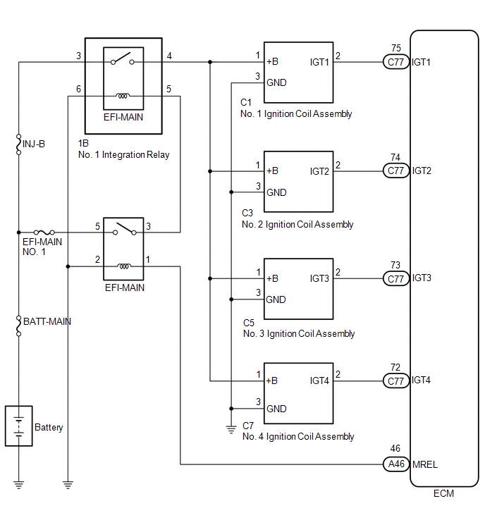
Ignition Circuit |
DESCRIPTION
A direct ignition system is used on this vehicle. The direct ignition system is a 1 cylinder ignition system which ignites one cylinder with one ignition coil. In the 1 cylinder ignition system, one spark plug is connected to the end of the secondary winding. High voltage is generated in the secondary winding and is applied directly to the spark plug. The spark of the spark plug passes from the center electrode to the ground electrode.
The ECM determines the ignition timing and transmits the ignition signals for each cylinder. Using the ignition signal, the ECM turns on and off the power transistor inside the igniter, which switches on and off a current to the primary coil. When the current to the primary coil is cut off, high voltage is generated in the secondary coil and this voltage is applied to the spark plugs to create sparks inside the cylinders.
WIRING DIAGRAM
CAUTION / NOTICE / HINT
NOTICE:
Inspect the fuses for circuits related to this system before performing the following procedure.
HINT:
Perform a spark test before proceeding. If there is no spark for any cylinder, inspect this circuit.
Click here
![2020 - 2023 MY Corolla [01/2019 - 11/2022]; 2ZR-FAE (ENGINE CONTROL): IGNITION SYSTEM: ON-VEHICLE INSPECTION+](/t3Portal/stylegraphics/info.gif)
PROCEDURE
|
1. |
CHECK TERMINAL VOLTAGE (POWER SOURCE OF IGNITION COIL ASSEMBLY) |
|
(a) Disconnect the ignition coil assembly connectors. |
|
(b) Turn the ignition switch to ON.
(c) Measure the voltage according to the value(s) in the table below.
Standard Voltage:
|
Tester Connection |
Condition |
Specified Condition |
|---|---|---|
|
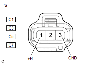
C1-1 (+B) - C1-3 (GND) |
Ignition switch ON |
11 to 14 V |
|
C3-1 (+B) - C3-3 (GND) |
Ignition switch ON |
11 to 14 V |
|
C5-1 (+B) - C5-3 (GND) |
Ignition switch ON |
11 to 14 V |
|
C7-1 (+B) - C7-3 (GND) |
Ignition switch ON |
11 to 14 V |
| NG |

|
|

|
2. |
CHECK HARNESS AND CONNECTOR (IGNITION COIL ASSEMBLY - ECM) |
(a) Disconnect the ignition coil assembly connectors.
(b) Disconnect the ECM connector.
(c) Measure the resistance according to the value(s) in the table below.
Standard Resistance:
|
Tester Connection |
Condition |
Specified Condition |
|---|---|---|
|
C1-2 (IGT1) - C77-75 (IGT1) |
Always |
Below 1 Ω |
|
C3-2 (IGT2) - C77-74 (IGT2) |
Always |
Below 1 Ω |
|
C5-2 (IGT3) - C77-73 (IGT3) |
Always |
Below 1 Ω |
|
C7-2 (IGT4) - C77-72 (IGT4) |
Always |
Below 1 Ω |
|
C1-2 (IGT1) or C77-75 (IGT1) - Body ground and other terminals |
Always |
10 kΩ or higher |
|
C3-2 (IGT2) or C77-74 (IGT2) - Body ground and other terminals |
Always |
10 kΩ or higher |
|
C5-2 (IGT3) or C77-73 (IGT3) - Body ground and other terminals |
Always |
10 kΩ or higher |
|
C7-2 (IGT4) or C77-72 (IGT4) - Body ground and other terminals |
Always |
10 kΩ or higher |
| OK |
|
REPLACE ECM
|
| NG |
|
REPAIR OR REPLACE HARNESS OR CONNECTOR |
|
3. |
CHECK HARNESS AND CONNECTOR (IGNITION COIL ASSEMBLY - BODY GROUND) |
(a) Disconnect the ignition coil assembly connectors.
(b) Measure the resistance according to the value(s) in the table below.
Standard Resistance:
|
Tester Connection |
Condition |
Specified Condition |
|---|---|---|
|
C1-3 (GND) - Body ground |
Always |
Below 1 Ω |
|
C3-3 (GND) - Body ground |
Always |
Below 1 Ω |
|
C5-3 (GND) - Body ground |
Always |
Below 1 Ω |
|
C7-3 (GND) - Body ground |
Always |
Below 1 Ω |
| NG |
|
REPAIR OR REPLACE HARNESS OR CONNECTOR |
|
|
4. |
CHECK HARNESS AND CONNECTOR (NO. 1 INTEGRATION RELAY - IGNITION COIL ASSEMBLY) |
(a) Disconnect the No. 1 integration relay connector.
(b) Disconnect the ignition coil assembly connectors.
(c) Measure the resistance according to the value(s) in the table below.
Standard Resistance:
|
Tester Connection |
Condition |
Specified Condition |
|---|---|---|
|
1B-4 - C1-1 (+B) |
Always |
Below 1 Ω |
|
1B-4 - C3-1 (+B) |
Always |
Below 1 Ω |
|
1B-4 - C5-1 (+B) |
Always |
Below 1 Ω |
|
1B-4 - C7-1 (+B) |
Always |
Below 1 Ω |
|
1B-4 - or C1-1 (+B) - Body ground and other terminals |
Always |
10 kΩ or higher |
|
1B-4 - or C3-1 (+B) - Body ground and other terminals |
Always |
10 kΩ or higher |
|
1B-4 - or C5-1 (+B) - Body ground and other terminals |
Always |
10 kΩ or higher |
|
1B-4 - or C7-1 (+B) - Body ground and other terminals |
Always |
10 kΩ or higher |
| NG |
|
REPAIR OR REPLACE HARNESS OR CONNECTOR (NO. 1 INTEGRATION RELAY - IGNITION COIL ASSEMBLY) |
|
|
5. |
CHECK TERMINAL VOLTAGE (POWER SOURCE OF NO. 1 INTEGRATION RELAY) |
|
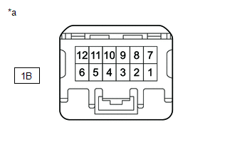
*a |
Front view of wire harness connector (to No. 1 Integration Relay) |
(a) Disconnect the No. 1 integration relay connector.
(b) Measure the voltage according to the value(s) in the table below.
Standard Voltage:
|
Tester Connection |
Condition |
Specified Condition |
|---|---|---|
|
1B-3 - Body ground |
Always |
11 to 14 V |
| NG |
|
REPAIR OR REPLACE HARNESS OR CONNECTOR (BATTERY - NO. 1 INTEGRATION RELAY) |
|
|
6. |
INSPECT NO. 1 INTEGRATION RELAY (EFI-MAIN RELAY) |
(a) Inspect the No. 1 integration relay (EFI-MAIN relay).
Click here
| NG |
|
REPLACE NO. 1 INTEGRATION RELAY
|
|
|
7. |
CHECK HARNESS AND CONNECTOR (NO. 1 INTEGRATION RELAY - BODY GROUND) |
(a) Disconnect the No. 1 integration relay connector.
(b) Measure the resistance according to the value(s) in the table below.
Standard Resistance:
|
Tester Connection |
Condition |
Specified Condition |
|---|---|---|
|
1B-6 - Body ground |
Always |
Below 1 Ω |
| NG |
|
REPAIR OR REPLACE HARNESS OR CONNECTOR |
|
|
8. |
CHECK HARNESS AND CONNECTOR (EFI-MAIN RELAY - NO. 1 INTEGRATION RELAY) |
(a) Remove the EFI-MAIN relay from the No. 1 engine room relay block and No. 1 junction block assembly.
(b) Disconnect the No. 1 integration relay connector.
(c) Measure the resistance according to the value(s) in the table below.
Standard Resistance:
|
Tester Connection |
Condition |
Specified Condition |
|---|---|---|
|
3 (EFI-MAIN relay) - 1B-5 |
Always |
Below 1 Ω |
|
3 (EFI-MAIN relay) or 1B-5 - Body ground and other terminals |
Always |
10 kΩ or higher |
| OK |
|
GO TO ECM POWER SOURCE CIRCUIT
|
| NG |
|
REPAIR OR REPLACE HARNESS OR CONNECTOR |
|
|
|