- Clear zero point calibration data.
- Perform yaw rate and acceleration sensor zero point calibration.
| Last Modified: 07-31-2024 | 6.11:8.1.0 | Doc ID: RM100000001GJSR |
| Model Year Start: 2020 | Model: GR Corolla | Prod Date Range: [01/2019 - 09/2022] |
| Title: STEERING GEAR / LINKAGE: STEERING GEAR: REMOVAL; 2020 - 2022 MY Corolla Corolla Hatchback Corolla HV GR Corolla [01/2019 - 09/2022] | ||
REMOVAL
CAUTION / NOTICE / HINT
The necessary procedures (adjustment, calibration, initialization, or registration) that must be performed after parts are removed and installed, or replaced during steering gear assembly removal/installation are shown below.
Necessary Procedures After Parts Removed/Installed/Replaced (for HV Model)
|
Replaced Part or Performed Procedure |
Necessary Procedure |
Effect/Inoperative Function when Necessary Procedure not Performed |
Link |
|---|---|---|---|
|
Front wheel alignment adjustment |
|
|
Necessary Procedures After Parts Removed/Installed/Replaced (for Gasoline Model)
|
Replaced Part or Performed Procedure |
Necessary Procedure |
Effect/Inoperative Function when Necessary Procedure not Performed |
Link |
|---|---|---|---|
|
Front wheel alignment adjustment |
|
|
w/ Electric Parking Brake System: w/o Electric Parking Brake System: |
|
Suspension, tires, etc. (If the vehicle height has changed due to suspension or tire replacement) |
Perform headlight ECU sub-assembly LH initialization |
Lighting system (w/ AFS)(EXT) |
PROCEDURE
1. ALIGN FRONT WHEELS FACING STRAIGHT AHEAD
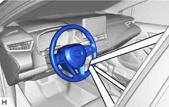
2. SECURE STEERING WHEEL
|
(a) Secure the steering wheel with the seat belt in order to prevent rotation. HINT: This operation is useful to prevent damage to the spiral cable. |
|
3. REMOVE COLUMN HOLE COVER SILENCER SHEET
4. SEPARATE NO. 2 STEERING INTERMEDIATE SHAFT ASSEMBLY
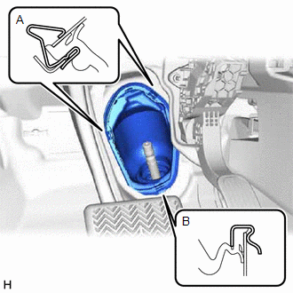
5. SEPARATE NO. 1 STEERING COLUMN HOLE COVER SUB-ASSEMBLY
|
(a) Separate the clip (A), disengage the clip (B) from the vehicle body and separate the No. 1 steering column hole cover sub-assembly. NOTICE: Do not damage the clips (A) or (B). |
|
6. REMOVE FRONT WHEELS
7. REMOVE NO. 1 ENGINE UNDER COVER ASSEMBLY
8. REMOVE REAR ENGINE UNDER COVER LH
9. REMOVE REAR ENGINE UNDER COVER RH
10. REMOVE REAR SIDE RAIL REINFORCEMENT SUB-ASSEMBLY LH
11. REMOVE REAR SIDE RAIL REINFORCEMENT SUB-ASSEMBLY RH
HINT:
Perform the same procedure as for the LH side.
12. SEPARATE FRONT STABILIZER LINK ASSEMBLY LH
13. SEPARATE FRONT STABILIZER LINK ASSEMBLY RH
HINT:
Perform the same procedure as for the LH side.
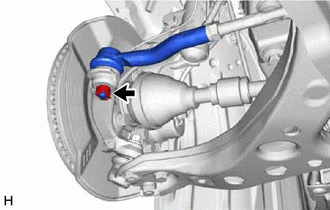
14. SEPARATE TIE ROD END SUB-ASSEMBLY LH
|
(a) Remove the cotter pin and nut. |
|
|
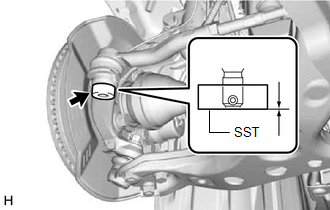
(b) Install SST to the tie rod end sub-assembly LH. SST: 09960-20010 09961-02060 NOTICE: Make sure that the upper ends of the tie rod end sub-assembly LH and SST are aligned. |
|
(c) Secure SST using a string.
NOTICE:
Be sure to tighten the string firmly to secure SST to the steering knuckle LH to prevent SST from falling off.
(d) Using SST, separate the tie rod end sub-assembly LH from the steering knuckle LH.
SST: 09960-20010
09961-02010
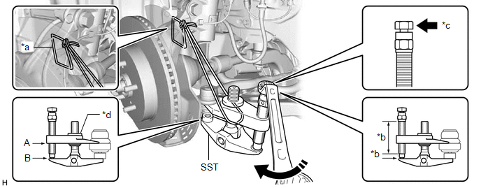
|
*a |
String |
*b |
Molybdenum Grease Application Area |
|
*c |
Place wrench here |
*d |
Center Nut |

|
Turn |
- |
- |
CAUTION:
Apply molybdenum grease to the bolt threads and the tip of SST.
NOTICE:
- Be sure to tighten the string firmly to secure SST to the steering knuckle LH to prevent SST from falling off.
- Install SST with the center nut so that (A) and (B) shown in the illustration are parallel. Otherwise, the ball joint dust cover may be damaged.
- Be sure to place the wrench on the part shown in the illustration.
- Do not damage the front disc brake dust cover.
- Do not damage the ball joint dust cover.
- Do not damage the steering knuckle LH.
15. SEPARATE TIE ROD END SUB-ASSEMBLY RH
HINT:
Perform the same procedure as for the LH side.
16. SEPARATE FRONT LOWER NO. 1 SUSPENSION ARM SUB-ASSEMBLY LH
17. SEPARATE FRONT LOWER NO. 1 SUSPENSION ARM SUB-ASSEMBLY RH
HINT:
Perform the same procedure as for the LH side.
18. REMOVE FRONT SUSPENSION CROSSMEMBER SUB-ASSEMBLY
19. REMOVE NO. 1 STEERING COLUMN HOLE COVER SUB-ASSEMBLY
(a) Remove the No. 1 steering column hole cover sub-assembly from the steering link assembly.
20. REMOVE STEERING LINK ASSEMBLY
|
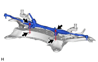
(a) Remove the 2 bolts, 2 nuts and steering link assembly from the front suspension crossmember sub-assembly. NOTICE: Because the nut has its own stopper, do not turn the nut. Loosen the bolt with the nut secured. |
|
21. SECURE STEERING LINK ASSEMBLY
|
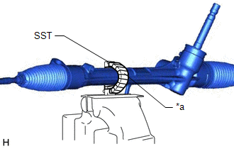
(a) Using SST, secure the steering link assembly in a vise. SST: 09612-00012 HINT: Wrap SST with protective tape before use. |
|
22. REMOVE TIE ROD END SUB-ASSEMBLY LH
|
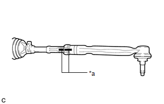
(a) Put matchmarks on the tie rod end sub-assembly LH and steering gear assembly. |
|
(b) Remove the tie rod end sub-assembly LH and lock nut.
23. REMOVE TIE ROD END SUB-ASSEMBLY RH
HINT:
Perform the same procedure as for the LH side.
|
|
|
![2020 - 2022 MY Corolla Corolla HV [01/2019 - 09/2022]; BRAKE CONTROL / DYNAMIC CONTROL SYSTEMS: ELECTRONICALLY CONTROLLED BRAKE SYSTEM (for HV Model): CALIBRATION](/t3Portal/stylegraphics/info.gif)
