- Clear zero point calibration data.
- Perform yaw rate and acceleration sensor zero point calibration.
| Last Modified: 01-27-2025 | 6.11:8.1.0 | Doc ID: RM100000001GJE8 |
| Model Year Start: 2020 | Model: GR Corolla | Prod Date Range: [01/2019 - 09/2022] |
| Title: FRONT SUSPENSION: FRONT SUSPENSION MEMBER: REMOVAL; 2020 - 2022 MY Corolla Corolla Hatchback Corolla HV GR Corolla [01/2019 - 09/2022] | ||
REMOVAL
CAUTION / NOTICE / HINT
The necessary procedures (adjustment, calibration, initialization, or registration) that must be performed after parts are removed and installed, or replaced during front suspension crossmember sub-assembly removal/installation are shown below.
Necessary Procedures After Parts Removed/Installed/Replaced (for HV Model)
|
Replaced Part or Performed Procedure |
Necessary Procedure |
Effect/Inoperative Function when Necessary Procedure not Performed |
Link |
|---|---|---|---|
|
Front wheel alignment adjustment |
|
|
|
Necessary Procedures After Parts Removed/Installed/Replaced (for Gasoline Model)
|
Replaced Part or Performed Procedure |
Necessary Procedure |
Effect/Inoperative Function when Necessary Procedure not Performed |
Link |
|---|---|---|---|
|
Front wheel alignment adjustment |
|
|
w/ Electric Parking Brake System:
w/o Electric Parking Brake System:
|
|
Suspension, tires, etc. (If the vehicle height has changed due to suspension or tire replacement) |
Perform headlight ECU sub-assembly LH initialization |
Lighting system (w/ AFS)(EXT) |
|
PROCEDURE
1. ALIGN FRONT WHEELS FACING STRAIGHT AHEAD
2. SECURE STEERING WHEEL
Click here
![2020 - 2022 MY Corolla Corolla Hatchback Corolla HV GR Corolla [01/2019 - 09/2022]; STEERING GEAR / LINKAGE: STEERING GEAR: REMOVAL+](/t3Portal/stylegraphics/info.gif)
3. REMOVE COLUMN HOLE COVER SILENCER SHEET
Click here
4. SEPARATE NO. 2 STEERING INTERMEDIATE SHAFT ASSEMBLY
Click here
5. SEPARATE NO. 1 STEERING COLUMN HOLE COVER SUB-ASSEMBLY
Click here
6. REMOVE FRONT WHEELS
Click here
7. REMOVE NO. 1 ENGINE UNDER COVER ASSEMBLY
for M20A-FKS: Click here
for 2ZR-FAE: Click here
for 2ZR-FXE: Click here
8. REMOVE REAR ENGINE UNDER COVER LH
for M20A-FKS: Click here
for 2ZR-FAE: Click here
for 2ZR-FXE: Click here
9. REMOVE REAR ENGINE UNDER COVER RH
for M20A-FKS: Click here
for 2ZR-FAE: Click here
for 2ZR-FXE: Click here
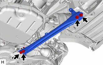
10. REMOVE REAR SIDE RAIL REINFORCEMENT SUB-ASSEMBLY LH
|
(a) Remove the 4 bolts and rear side rail reinforcement sub-assembly LH from the front suspension crossmember sub-assembly and vehicle body. |
|
11. REMOVE REAR SIDE RAIL REINFORCEMENT SUB-ASSEMBLY RH
HINT:
Perform the same procedure as for the LH side.
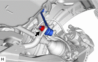
12. SEPARATE FRONT STABILIZER LINK ASSEMBLY LH
|
(a) Remove the nut and separate front stabilizer link assembly LH from the front stabilizer bar. NOTICE: Do not damage the boot of the ball joint. HINT: If the ball joint turns together with the nut, use a 6 mm hexagon socket wrench to hold the stud bolt. |
|
13. SEPARATE FRONT STABILIZER LINK ASSEMBLY RH
HINT:
Perform the same procedure as for the LH side.
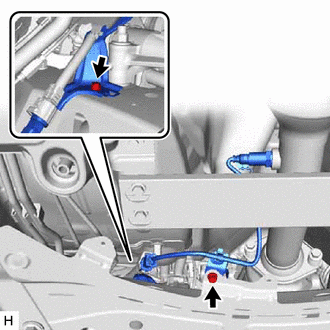
14. SEPARATE TIE ROD END SUB-ASSEMBLY LH
Click here
15. SEPARATE TIE ROD END SUB-ASSEMBLY RH
HINT:
Perform the same procedure as for the LH side.
16. SEPARATE FRONT LOWER NO. 1 SUSPENSION ARM SUB-ASSEMBLY LH
Click here
17. SEPARATE FRONT LOWER NO. 1 SUSPENSION ARM SUB-ASSEMBLY RH
HINT:
Perform the same procedure as for the LH side.
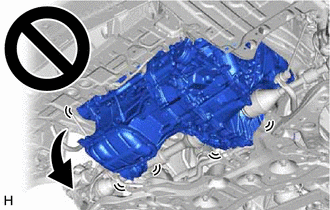
18. REMOVE FRONT SUSPENSION CROSSMEMBER SUB-ASSEMBLY
|
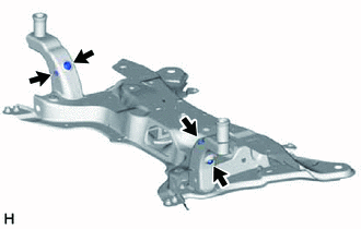
(a) Remove the 2 bolts and separate the 2 wire harness clamp brackets from the front suspension crossmember sub-assembly. |
|
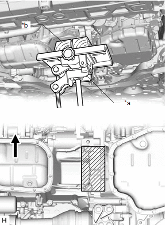
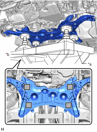
(b) Using a transmission jack and a wooden block, support the engine assembly with transaxle.
|
*a |
Transmission Jack |
|
*b |
Wooden Block |

|
Front of the Vehicle |

|
Wooden block placement location |
CAUTION:
- Support the engine assembly with transaxle until the front suspension crossmember sub-assembly is installed.
- If the support is removed before the front suspension crossmember sub-assembly is installed, the engine assembly with transaxle may drop.
|
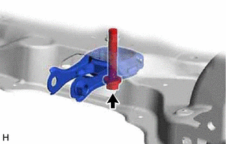
(c) Remove the bolt and separate the engine moving control rod. |
|
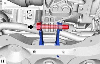
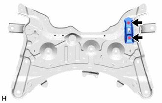
(d) Support the front suspension crossmember sub-assembly with an engine lifter using 4 attachments or equivalent tools as shown in the illustration.
|
*a |
Engine Lifter |
|
*b |
Attachment |
|
|
Attachment placement location |
CAUTION:
- The front suspension crossmember sub-assembly is a very heavy component. Make sure that it is supported securely.
- If the front suspension crossmember sub-assembly is not securely supported, it may drop, resulting in serious injury.
NOTICE:
Use attachments to keep the front suspension crossmember sub-assembly level.
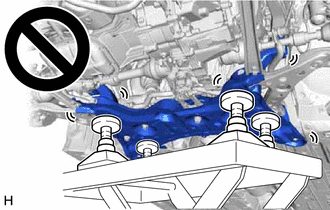
(e) Remove the 4 bolts and front suspension crossmember sub-assembly.
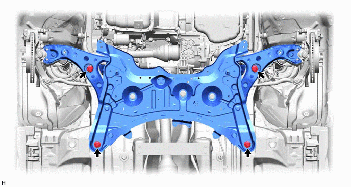
(f) Slowly lower the front suspension crossmember sub-assembly.
NOTICE:
When lowering the front suspension crossmember sub-assembly, be careful not to damage the vehicle body or other components installed to the vehicle.
19. REMOVE STEERING LINK ASSEMBLY
Click here
20. REMOVE FRONT NO. 1 STABILIZER BRACKET LH
Click here
21. REMOVE FRONT NO. 1 STABILIZER BRACKET RH
HINT:
Perform the same procedure as for the LH side.
22. REMOVE FRONT STABILIZER BAR
Click here
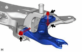
23. REMOVE ENGINE MOVING CONTROL ROD
|
(a) Remove the bolt and engine moving control rod from the front suspension crossmember sub-assembly. |
|
24. REMOVE FRONT LOWER NO. 1 SUSPENSION ARM SUB-ASSEMBLY LH
|
(a) Remove the 2 bolts, nut and front lower No. 1 suspension arm sub-assembly LH from the front suspension crossmember sub-assembly. NOTICE: Because the nut has its own stopper, do not turn the nut. Loosen the bolt with the nut secured. |
|
25. REMOVE FRONT LOWER NO. 1 SUSPENSION ARM SUB-ASSEMBLY RH
HINT:
Perform the same procedure as for the LH side.
26. REMOVE FRONT SUSPENSION MEMBER PLATE
|
(a) Remove the 2 front suspension member plates from the front suspension crossmember sub-assembly. |
|
27. REMOVE HOLE PLUG
|
(a) Remove the 4 hole plugs from the front suspension crossmember sub-assembly. HINT: There are 2 different shapes of hole plug. |
|
28. REMOVE FRONT DIFFERENTIAL SUPPORT GUARD LH (w/ Differential Support Guard)
|
(a) Remove the 2 bolts and front differential support guard LH from the front suspension crossmember sub-assembly. |
|
|
|
|