| Last Modified: 05-13-2024 | 6.11:8.1.0 | Doc ID: RM100000001GHBC |
| Model Year Start: 2020 | Model: Corolla | Prod Date Range: [01/2019 - 04/2020] |
| Title: 2ZR-FAE (ENGINE CONTROL): SFI SYSTEM: FREEZE FRAME DATA; 2020 MY Corolla [01/2019 - 04/2020] | ||
FREEZE FRAME DATA
DESCRIPTION
The ECM records vehicle and driving condition information as Freeze Frame Data the moment a DTC is stored. When troubleshooting, Freeze Frame Data can be helpful in determining whether the vehicle was moving or stationary, whether the engine was warmed up or not, whether the air fuel ratio was lean or rich, as well as other data recorded at the time of a malfunction.
HINT:
If it is impossible to replicate the problem even though a DTC is detected, confirm the Freeze Frame Data.
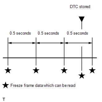
The ECM records engine conditions in the form of Freeze Frame Data every 0.5 seconds. Using the Techstream, 5 separate sets of Freeze Frame Data can be checked.
- 3 data sets before the DTC was stored.
- 1 data set when the DTC was stored.
- 1 data set after the DTC was stored.
These data sets can be used to simulate the condition of the vehicle around the time of the occurrence the malfunction. The data may assist in identifying the cause of the malfunction, and judging whether it was temporary or not.
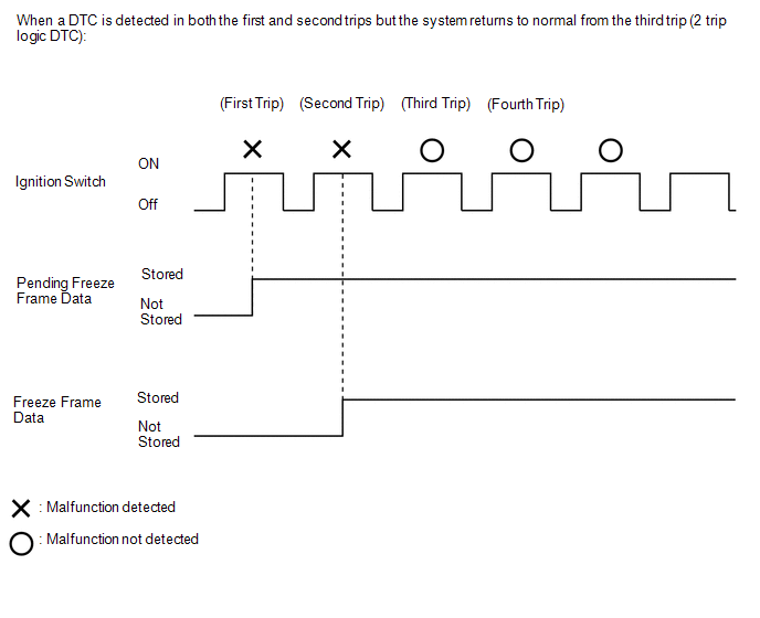
PENDING FREEZE FRAME DATA
HINT:
Pending Freeze Frame Data is stored when a 2 trip DTC is first detected during the first trip.
(a) Connect the Techstream to the DLC3.
(b) Turn the ignition switch to ON.
(c) Turn the Techstream on.
(d) Enter the following menus: Powertrain / Engine and ECT / Trouble Codes.
Powertrain > Engine and ECT > Trouble Codes
(e) Select a DTC in order to display its pending Freeze Frame Data.
HINT:
-
Pending Freeze Frame Data is cleared when any of the following occurs.
- Using the Techstream, the DTCs cleared.
- The cable is disconnected from the negative (-) battery terminal.
- 40 trips with the engine fully warmed up have been performed after returning to normal. (Pending Freeze Frame Data will not be cleared by only returning the system to normal.)
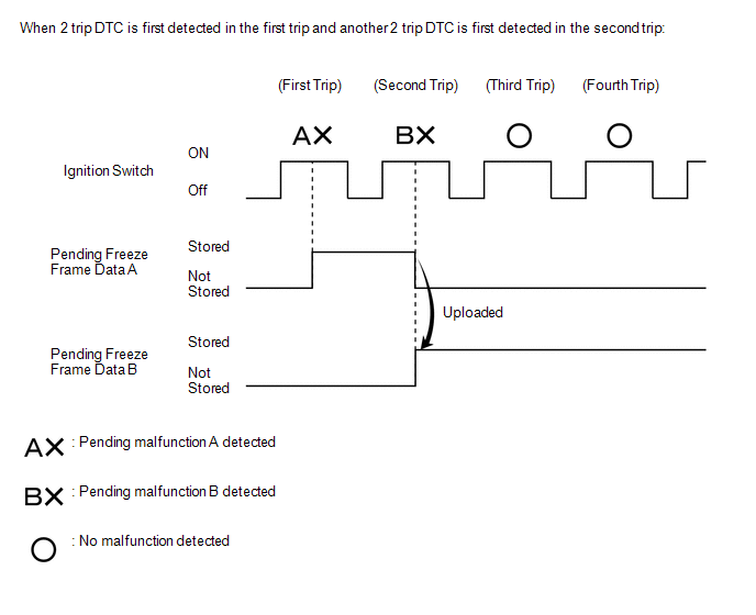
- With previous pending Freeze Frame Data stored, if pending Freeze Frame Data is newly stored when a 2 trip DTC is detected in the first trip, the old Freeze Frame Data will be replaced with the new data of the newly detected DTC in the next trip.
LIST OF FREEZE FRAME DATA
Powertrain > Engine and ECT
|
Tester Display |
|---|
|
Vehicle Speed |
|
Engine Speed |
|
Calculate Load |
|
Vehicle Load |
|
MAF |
|
Atmosphere Pressure |
|
MAP |
|
Engine Oil Temperature Sensor |
|
Coolant Temp |
|
Intake Air |
|
Ambient Temperature |
|
Engine Run Time |
|
Initial Engine Coolant Temp |
|
Coolant Temp Variation after Waterpump Start |
|
Initial Intake Air Temp |
|
Intake Air Temp Variation after Engine Start |
|
Battery Voltage |
|
Glow Indicator Supported |
|
Glow Indicator |
|
Accel Sens. No.1 Volt % |
|
Accel Sens. No.2 Volt % |
|
Throttle Sensor Volt % |
|
Throttle Sensor #2 Volt % |
|
Throttle Sensor Position |
|
Throttle Motor DUTY |
|
Throttle Air Flow Learning Value(Area 1) |
|
Throttle Air Flow Learning Value(Area 2) |
|
Throttle Air Flow Learning Value(Area 3) |
|
Throttle Air Flow Learning Value(Calculated Value) |
|
Throttle Air Flow Learning Value(Atmosphere Pressure Offset Value) |
|
Throttle Air Flow Learning Prohibit(Intake Air Pressure Malfunction) |
|
Throttle Air Flow Learning Prohibit(Air Fuel Ratio Malfunction) |
|
Throttle Position |
|
ISC Flow |
|
ISC Position |
|
ISC Feedback Value |
|
ISC Learning Value |
|
Electric Load Feedback Val |
|
Air Conditioner FB Val |
|
Low Revolution Control |
|
Neutral Control |
|
N Range Status |
|
Eng Stall Control FB Flow |
|
Injector (Port) |
|
Injection Volum (Cylinder1) |
|
Fuel Pump/Speed Status |
|
Vacuum Pump |
|
Current Fuel Type |
|
EVAP (Purge) VSV |
|
Evap Purge Flow |
|
Purge Density Learn Value |
|
EVAP System Vent Valve |
|
EVAP Purge VSV |
|
Purge Cut VSV Duty |
|
Target Air-Fuel Ratio |
|
AF Lambda B1S1 |
|
AFS Voltage B1S1 |
|
AFS Current B1S1 |
|
A/F Heater Duty B1S1 |
|
O2S B1S2 |
|
O2S Impedance B1S2 |
|
O2 Heater B1S2 |
|
O2 Heater Curr Val B1S2 |
|
Short FT B1S1 |
|
Short FT B1S2 |
|
Long FT B1S1 |
|
Long FT B1S2 |
|
Total FT #1 |
|
Fuel System Status #1 |
|
Fuel System Status #2 |
|
IGN Advance |
|
Knock Feedback Value |
|
Knock Correct Learn Value |
|
Idle Spark Advn Ctrl #1 |
|
Idle Spark Advn Ctrl #2 |
|
Idle Spark Advn Ctrl #3 |
|
Idle Spark Advn Ctrl #4 |
|
VVT Control Status #1 |
|
VVT Advance Fail |
|
VALVEMATIC Target Angle |
|
VALVEMATIC Current Angle |
|
VALVEMATIC Shaft Sensor Voltage |
|
VALVEMATIC IG OFF |
|
VALVEMATIC IG ON |
|
VALVEMATIC Cranking |
|
VALVEMATIC bef Warm Up |
|
VALVEMATIC aft Warm Up |
|
VALVEMATIC IDM Hi Temp |
|
VALVEMATIC Low(ACT) |
|
VALVEMATIC High(ACT) |
|
Catalyst Temp B1S1 |
|
Catalyst Temp B1S2 |
|
Starter Signal |
|
Power Steering Signal |
|
Neutral Position SW Signal |
|
Neutral Position SW Signal |
|
Clutch Switch |
|
Stop Light Switch |
|
A/C Signal |
|
Closed Throttle Position SW |
|
Fuel Cut Condition |
|
Immobiliser Communication |
|
Time after DTC Cleared |
|
Distance from DTC Cleared |
|
Warmup Cycle Cleared DTC |
|
Dist Batt Cable Disconnect |
|
IG OFF Elapsed Time |
|
TC and TE1 |
|
Total Distance Traveled |
|
Ignition Trig. Count |
|
Cylinder #1 Misfire Count |
|
Cylinder #2 Misfire Count |
|
Cylinder #3 Misfire Count |
|
Cylinder #4 Misfire Count |
|
All Cylinders Misfire Count |
|
Misfire RPM |
|
Misfire Load |
|
Misfire Margin |
|
Catalyst OT MF F/C |
|
Cat OT MF F/C History |
|
Cat OT MF F/C Cylinder#1 |
|
Cat OT MF F/C Cylinder#2 |
|
Cat OT MF F/C Cylinder#3 |
|
Cat OT MF F/C Cylinder#4 |
|
Engine Speed (Starter Off) |
|
Starter Count |
|
Run Dist of Previous Trip |
|
Compression Leakage Count |
|
Rough Idle Status |
|
Plural Cylinders Rough Idle |
|
Rough Idle #1 |
|
Rough Idle #2 |
|
Rough Idle #3 |
|
Rough Idle #4 |
|
Engine Starting Time |
|
Previous Trip Coolant Temp |
|
Previous Trip Intake Temp |
|
Engine Oil Temperature |
|
Previous Trip Eng Oil Temp |
|
Ambient Temp for A/C |
|
Previous Trip Ambient Temp |
|
Engine Start Hesitation |
|
Low Rev for Eng Start |
|
Minimum Engine Speed |
|
Fuel Cut Elps Time |
|
A/F Learn Value Idle #1 |
|
A/F Learn Value Low #1 |
|
A/F Learn Value Mid1 #1 |
|
A/F Learn Value Mid2 #1 |
|
A/F Learn Value High #1 |
|
Electric Fan Motor |
|
Electric Cooling Fan Drive Count when IG OFF |
|
Brake Override System |
|
Idle Fuel Cut |
|
FC TAU |
|
Immobiliser Fuel Cut |
|
Immobiliser Fuel Cut History |
|
Fuel Remaining Volume |
|
Comm with VALVEMATIC |
|
Electrical Load Signal 1 |
|
Electrical Load Signal 2 |
|
Cruise Main SW |
|
A/F Sensor Determination (worst value) #1 |
|
Engine Speed Fluctuation Avg (worst value) #1 |
|
Engine Speed Fluctuation Avg (worst value) #2 |
|
Engine Speed Fluctuation Avg (worst value) #3 |
|
Engine Speed Fluctuation Avg (worst value) #4 |
|
Shift SW Status (R Range) |
|
|
|