| Last Modified: 07-31-2024 | 6.11:8.1.0 | Doc ID: RM100000001GCQ3 |
| Model Year Start: 2020 | Model: Corolla | Prod Date Range: [01/2019 - 04/2020] |
| Title: HYBRID / BATTERY CONTROL: FRAME WIRE: INSTALLATION; 2020 MY Corolla Corolla HV [01/2019 - 04/2020] | ||
INSTALLATION
PROCEDURE
1. INSTALL HV FLOOR UNDER WIRE
CAUTION:
Be sure to wear insulated gloves.
|
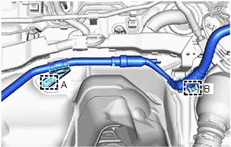
(a) Engage the clamp (B). |
|
(b) Install a new clamp (A).
|
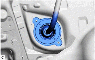
(c) Insert the HV floor under wire into the floor panel hole and engage the grommet. |
|
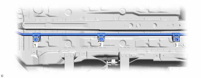
(d) Install 3 new clamps in the order shown in the illustration.
|
(e) Install the HV floor under wire with the 2 nuts. Torque: 8.5 N·m {87 kgf·cm, 75 in·lbf} |
|
2. INSTALL FRONT SUSPENSION CROSSMEMBER SUB-ASSEMBLY
3. INSTALL FRONT FLOOR COVER RH
HINT:
Perform the same procedure as for the front floor cover LH.
4. INSTALL REAR FLOOR SIDE MEMBER COVER RH (w/ Cover)
5. CONNECT HV FLOOR UNDER WIRE
CAUTION:
Be sure to wear insulated gloves.
(a) Connect the shield ground to the HV battery.
(b) Connect the 2 HV battery junction block assembly connectors.
NOTICE:
Make sure that the connectors are connected securely.
6. INSTALL NO. 1 HV BATTERY COVER PANEL RH
7. INSTALL REAR SEAT CUSHION LEG SUB-ASSEMBLY
8. INSTALL REAR UNDER COVER
9. INSTALL REAR UNDER SIDE COVER LH
10. INSTALL REAR DOOR SCUFF PLATE LH
11. INSTALL REAR UNDER SIDE COVER RH
HINT:
Use the same procedure as for the LH side.
12. INSTALL REAR DOOR SCUFF PLATE RH
HINT:
Use the same procedure as for the LH side.
13. INSTALL REAR SEAT CUSHION LOCK HOOK
14. INSTALL REAR SEAT CUSHION ASSEMBLY
15. CONNECT REAR SEAT CENTER LAP TYPE BELT ASSEMBLY
16. CONNECT HV FLOOR UNDER WIRE
17. CONNECT ENGINE WIRE
CAUTION:
Be sure to wear insulated gloves.
NOTICE:
Do not allow any foreign matter or water to enter the inverter with converter assembly.
(a) Engage the 2 clamps and connect the engine wire.
(b) Install the bolt.
Torque:
8.0 N·m {82 kgf·cm, 71 in·lbf}
|
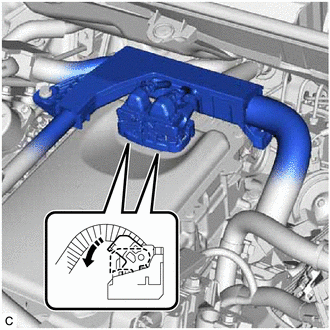
(c) Connect the 2 inverter with converter assembly connectors and move each lock lever as shown in the illustration. NOTICE:
|
|
18. INSTALL SERVICE PLUG GRIP
19. PERFORM INITIALIZATION
|
|
|
![2020 - 2022 MY Corolla Corolla Hatchback Corolla HV GR Corolla [01/2019 - 09/2022]; FRONT SUSPENSION: FRONT SUSPENSION MEMBER: INSTALLATION](/t3Portal/stylegraphics/info.gif)
