| Last Modified: 05-13-2024 | 6.11:8.1.0 | Doc ID: RM100000001GCPO |
| Model Year Start: 2020 | Model: Corolla | Prod Date Range: [01/2019 - 09/2022] |
| Title: HYBRID / BATTERY CONTROL: BATTERY VOLTAGE SENSOR (for NICKEL METAL HYDRIDE BATTERY): REMOVAL; 2020 - 2022 MY Corolla Corolla HV [01/2019 - 09/2022] | ||
REMOVAL
CAUTION / NOTICE / HINT
The necessary procedures (adjustment, calibration, initialization or registration) that must be performed after parts are removed and installed, or replaced during battery voltage sensor removal/installation are shown below.
Necessary Procedures After Parts Removed/Installed/Replaced
|
Replaced Part or Performed Procedure |
Necessary Procedure |
Effect/Inoperative Function when Necessary Procedure not Performed |
Link |
|---|---|---|---|
|
Auxiliary battery terminal is disconnected/reconnected |
Perform steering sensor zero point calibration |
Lane Control System |
|
|
Pre-collision System |
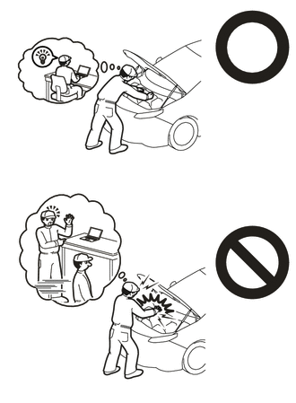
CAUTION:
NOTICE:
- After the power switch is turned off, the radio and display receiver assembly records various types of memory and settings. As a result, after turning the power switch off, make sure to wait at least 85 seconds before disconnecting the cable from the negative (-) auxiliary battery terminal. (for Audio and Visual System (for HV Model))
- The type of battery voltage sensor to be used varies depending on the vehicle model.
-
The type of battery voltage sensor can be confirmed by the color of the label.
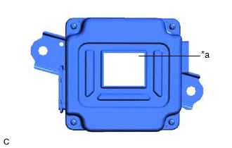
*a
Black Label
- If the wrong type of battery voltage sensor is installed, the power switch cannot be turned on (READY).
-
After installing the battery voltage sensor, perform the following to check that the power switch can be turned on (READY).
- Turn the power switch on (READY).
- Turn the power switch off and wait for 30 seconds or more.
- Turn the power switch on (READY) again.
PROCEDURE
1. REMOVE SERVICE PLUG GRIP
2. DISCONNECT ENGINE WIRE
3. REMOVE CONNECTOR COVER ASSEMBLY
4. CHECK TERMINAL VOLTAGE
5. INSTALL CONNECTOR COVER ASSEMBLY
6. CONNECT ENGINE WIRE
7. DISCONNECT REAR SEAT CENTER LAP TYPE BELT ASSEMBLY
8. REMOVE REAR SEAT CUSHION ASSEMBLY
9. REMOVE REAR SEAT CUSHION LOCK HOOK
10. REMOVE REAR DOOR SCUFF PLATE LH
11. REMOVE REAR UNDER SIDE COVER LH
12. REMOVE REAR DOOR SCUFF PLATE RH
HINT:
Use the same procedure as for the LH side.
13. REMOVE REAR UNDER SIDE COVER RH
HINT:
Use the same procedure as for the LH side.
14. REMOVE REAR UNDER COVER
15. REMOVE REAR SEAT CUSHION LEG SUB-ASSEMBLY
16. REMOVE BATTERY COOLING BLOWER ASSEMBLY
17. REMOVE NO. 1 HV BATTERY COVER PANEL RH
18. DISCONNECT FLOOR UNDER WIRE
19. DISCONNECT FLOOR WIRE
20. REMOVE NO. 1 HYBRID BATTERY EXHAUST DUCT
21. DISCONNECT FLOOR WIRE
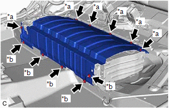
22. REMOVE UPPER NO. 1 HYBRID BATTERY COVER SUB-ASSEMBLY
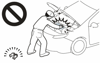
CAUTION:
Be sure to wear insulated gloves and protective goggles.
|
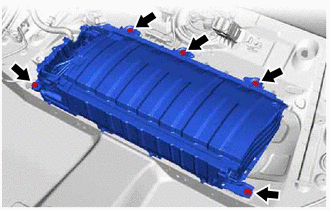
(a) Remove the 5 bolts. NOTICE:
|
|
|
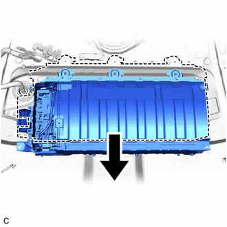
(b) Move the HV battery toward the front of the vehicle. |
|
|
(c) Remove the 6 bolts, 5 nuts and upper No. 1 hybrid battery cover sub-assembly from the HV battery. |
|
23. REMOVE NO. 1 HV BATTERY SHIELD PANEL
CAUTION:
Be sure to wear insulated gloves and protective goggles.
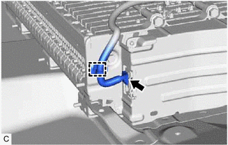
|
(a) Disengage the clamp. |
|
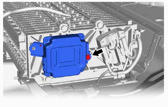
(b) Disconnect the battery voltage sensor connector.
|
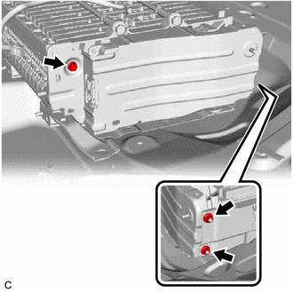
(c) Remove the bolt and 2 nuts. |
|
(d) Pull back the No. 2 hybrid battery shield sub-assembly and remove the No. 1 HV battery shield panel from the HV battery.
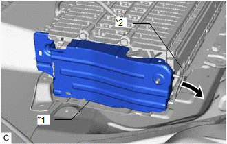
|
*1 |
No. 1 HV Battery Shield Panel |
|
*2 |
No. 2 Hybrid Battery Shield Sub-assembly |

|
Pull Back |
HINT:
Pull back the No. 2 hybrid battery shield sub-assembly until it is separated from the 2 stud bolts of the No. 1 HV battery shield panel.
24. REMOVE BATTERY VOLTAGE SENSOR
CAUTION:
Be sure to wear insulated gloves and protective goggles.
|
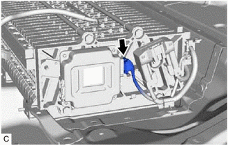
(a) Disconnect the battery voltage sensor connector. NOTICE: Insulate each disconnected high-voltage connector with insulating tape. Wrap the connector from the wire harness side to the end of the connector. |
|
|
(b) Remove the bolt and battery voltage sensor from the HV battery. NOTICE: If the battery voltage sensor has been struck or dropped, replace it. |
|
|
|
|
![2020 - 2022 MY Corolla Corolla HV [01/2019 - 09/2022]; PRE-COLLISION: PRE-COLLISION SYSTEM (for HV Model): INITIALIZATION](/t3Portal/stylegraphics/info.gif)
