| Last Modified: 07-31-2024 | 6.11:8.1.0 | Doc ID: RM100000001GCPK |
| Model Year Start: 2020 | Model: Corolla | Prod Date Range: [01/2019 - 04/2020] |
| Title: HYBRID / BATTERY CONTROL: INVERTER WITH CONVERTER: INSTALLATION; 2020 MY Corolla Corolla HV [01/2019 - 04/2020] | ||
INSTALLATION
PROCEDURE
1. INSTALL WIRE HARNESS CLAMP BRACKET
(a) Install the wire harness clamp bracket to the inverter with converter assembly with the bolt.
Torque:
8.0 N·m {82 kgf·cm, 71 in·lbf}
(b) Install the wire harness clamp bracket to the inverter with converter assembly with the bolt.
Torque:
8.0 N·m {82 kgf·cm, 71 in·lbf}
(c) Install the wire harness clamp bracket to the inverter with converter assembly with the bolt.
Torque:
8.0 N·m {82 kgf·cm, 71 in·lbf}
2. INSTALL TRANSMISSION CONTROL CABLE SUPPORT
(a) Install the transmission control cable support to the inverter with converter assembly with the bolt.
Torque:
5.0 N·m {51 kgf·cm, 44 in·lbf}
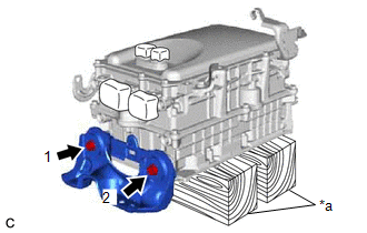
3. INSTALL NO. 2 INVERTER BRACKET
NOTICE:
Make sure to support the inverter with converter assembly at the positions shown in the illustration, otherwise it may be damaged.
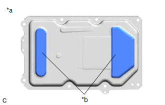
|
*a |
Bottom of Inverter with Converter Assembly |
|
*b |
Support |
|
(a) Set the inverter with converter assembly on wooden blocks. |
|
(b) Temporarily install the No. 2 inverter bracket to the inverter with converter assembly with the 2 bolts.
(c) Fully tighten the 2 bolts in the order shown in the illustration.
Torque:
15 N·m {153 kgf·cm, 11 ft·lbf}
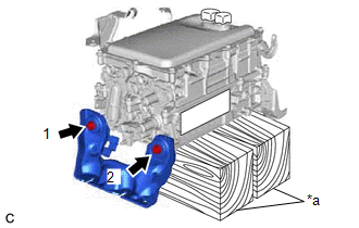
4. INSTALL NO. 1 INVERTER BRACKET
|
(a) Temporarily install the No. 1 inverter bracket to the inverter with converter assembly with the 2 bolts. |
|
(b) Fully tighten the 2 bolts in the order shown in the illustration.
Torque:
15 N·m {153 kgf·cm, 11 ft·lbf}
5. INSTALL INVERTER WITH CONVERTER ASSEMBLY
CAUTION:
Be sure to wear insulated gloves.
(a) Temporarily install the inverter with converter assembly with the 5 bolts and 2 nuts.
NOTICE:
- When installing the inverter with converter assembly, be careful not to damage the parts around it.
- To prevent damage, do not hold the inverter with converter assembly by the connectors, brackets or cooling pipes.
- To prevent damage due to static electricity, do not touch the terminals of the disconnected connectors.
-
Make sure that the inverter with converter assembly is positioned so that the stud bolts are in contact with the base of the U-shaped portions of the No. 1 inverter bracket.
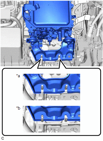
*a
Correct
*b
Incorrect
HINT:
If the bolts and nuts are not tightened appropriately, the inverter with converter assembly may make an abnormal noise.
(b) Fully tighten the bolt (A).
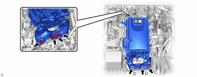
Torque:
25 N·m {255 kgf·cm, 18 ft·lbf}
(c) Fully tighten the 3 bolts (B).
Torque:
25 N·m {255 kgf·cm, 18 ft·lbf}
(d) Fully tighten the bolt (C).
Torque:
25 N·m {255 kgf·cm, 18 ft·lbf}
(e) Fully tighten the 2 nuts (D).
Torque:
25 N·m {255 kgf·cm, 18 ft·lbf}
6. CONNECT MOTOR CABLE
CAUTION:
Be sure to wear insulated gloves.
NOTICE:
Do not allow any foreign matter or water to enter the inverter with converter assembly.
(a) Temporarily connect the motor cable to the inverter with converter assembly with the 4 bolts.
NOTICE:
- Do not touch the waterproof seal or terminals of the connector.
- Do not damage the terminals, connector housing or inverter with converter assembly during connection.
|
(b) Fully tighten the bolt (A). Torque: 8.0 N·m {82 kgf·cm, 71 in·lbf} |
|
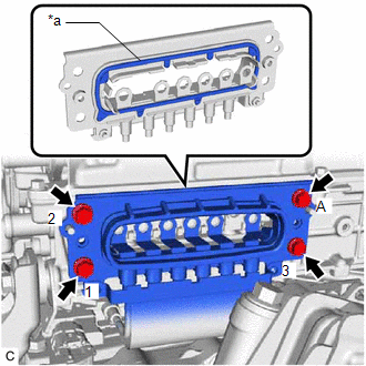
(c) Fully tighten the 3 bolts in the order shown in the illustration to connect the motor cable to the inverter with converter assembly.
Torque:
8.0 N·m {82 kgf·cm, 71 in·lbf}
|
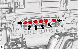
(d) Temporarily install the 6 bolts. NOTICE:
|
|
(e) Using an insulated tool, fully tighten the 6 bolts.
Torque:
8.0 N·m {82 kgf·cm, 71 in·lbf}
NOTICE:
- Do not touch the waterproof seal or terminals of the connector.
- Do not damage the terminals, connector housing or inverter with converter assembly during connection.
- Be sure to use a torque wrench to tighten the bolts.
7. INSTALL INVERTER COVER
CAUTION:
Be sure to wear insulated gloves.
(a) Install the inverter cover to the inverter with converter assembly with the 2 bolts.
Torque:
8.0 N·m {82 kgf·cm, 71 in·lbf}
NOTICE:
- Visually confirm that the inverter cover waterproof seal is securely installed before installing the inverter cover.
- Do not touch the waterproof seal of the inverter cover.
- Make sure that the interlock is fully engaged.
- Do not damage the terminals, interlock connector or inverter with converter assembly during installation.
- Do not allow any foreign matter or water to enter the inverter with converter assembly.
-
Do not remove or excessively tighten the screw of the inverter cover.
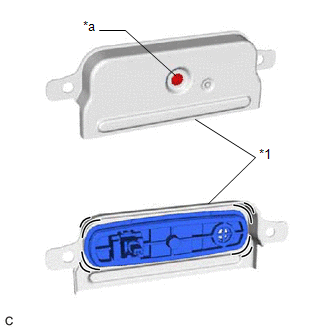
*1
Inverter Cover
*a
Screw
- Although the inverter cover may feel loose, this is not due to a malfunction.
-
Push in the inverter cover until it contacts the inverter with converter assembly.
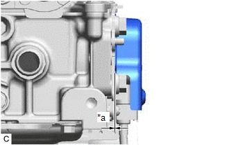
*a
No Gap
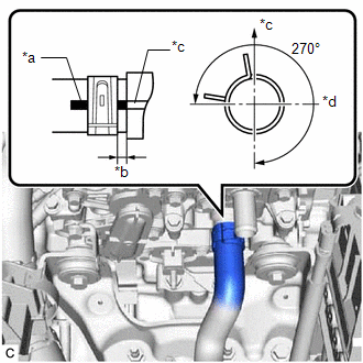
8. CONNECT INLET NO. 1 INVERTER COOLING HOSE
|
(a) Connect the inlet No. 1 inverter cooling hose to the inverter with converter assembly and slide the clip to secure it. NOTICE:
HINT: Make sure that the clip is positioned as shown in the illustration. |
|
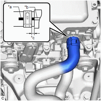
9. CONNECT OUTLET NO. 1 INVERTER COOLING HOSE
|
(a) Connect the outlet No. 1 inverter cooling hose to the inverter with converter assembly and slide the clip to secure it. NOTICE:
|
|
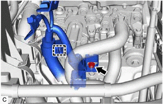
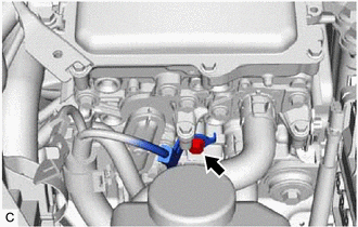
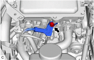
10. CONNECT NO. 3 ENGINE WIRE
CAUTION:
Be sure to wear insulated gloves.
|
(a) Engage the clamp and connect the No. 3 engine wire to the inverter with converter assembly. |
|
(b) Temporarily install the nut.
NOTICE:
To prevent the threads from being damaged, temporarily tighten the nut by hand.
(c) Fully tighten the nut.
Torque:
8.0 N·m {82 kgf·cm, 71 in·lbf}
(d) Engage the 2 claws to close the No. 3 engine wire terminal cover.
|
(e) Connect the No. 3 engine wire to the inverter with converter assembly with the bolt. Torque: 8.5 N·m {87 kgf·cm, 75 in·lbf} |
|
|
(f) Connect the No. 3 engine wire to the inverter with converter assembly with the bolt. Torque: 8.5 N·m {87 kgf·cm, 75 in·lbf} |
|
11. INSTALL WIRE HARNESS CLAMP BRACKET
(a) Install the wire harness clamp bracket to the inverter with converter assembly with the nut.
Torque:
8.0 N·m {82 kgf·cm, 71 in·lbf}
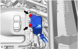
12. CONNECT HV AIR CONDITIONING WIRE
CAUTION:
Be sure to wear insulated gloves.
(a) Engage the clamp.
|
(b) Connect the HV air conditioning wire to the inverter with converter assembly and install the 2 bolts. Torque: 8.0 N·m {82 kgf·cm, 71 in·lbf} NOTICE:
|
|
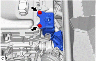
13. CONNECT FLOOR UNDER WIRE
CAUTION:
Be sure to wear insulated gloves.
(a) Engage the 2 clamps.
|
(b) Connect the HV floor under wire to the inverter with converter assembly and install the 2 bolts. Torque: 8.0 N·m {82 kgf·cm, 71 in·lbf} NOTICE:
|
|
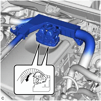
14. CONNECT ENGINE WIRE
CAUTION:
Be sure to wear insulated gloves.
NOTICE:
Do not allow any foreign matter or water to enter the inverter with converter assembly.
(a) Engage the clamp to connect the engine wire.
(b) Install the 2 bolts.
Torque:
8.0 N·m {82 kgf·cm, 71 in·lbf}
(c) Install the inverter protector to the inverter with converter assembly with the bolt.
Torque:
9.5 N·m {97 kgf·cm, 84 in·lbf}
(d) Engage the 2 clamps.
|
(e) Connect the 2 inverter with converter assembly connectors move the lock lever as shown in the illustration. NOTICE:
|
|
(f) Engage the 2 claws to connect the engine wire to the No. 1 engine room relay block.
(g) Connect the 3 No. 1 engine room relay block connectors.
(h) Install the No. 1 relay block cover to the No. 1 engine room relay block.
15. CONNECT FLOOR SHIFT TRANSMISSION CONTROL SELECT CABLE
(a) Engage the clamp to connect the floor shift transmission control select cable.
16. INSTALL BATTERY CLAMP SUB-ASSEMBLY
(a) Install the battery clamp sub-assembly to the vehicle with the 3 bolts.
Torque:
15.4 N·m {157 kgf·cm, 11 ft·lbf}
17. INSTALL ECM
18. INSTALL SERVICE PLUG GRIP
19. INSTALL AUXILIARY BATTERY
20. CONNECT ENGINE WIRE
(a) Connect the battery state sensor assembly connector.
(b) Engage the 2 claws to connect the engine wire to the battery current sensor holder.
21. ADD COOLANT (for Inverter)
22. INSPECT FOR COOLANT LEAK (for Inverter)
23. PERFORM RESOLVER LEARNING
|
|
|
![2020 - 2022 MY Corolla Corolla HV [01/2019 - 09/2022]; 2ZR-FXE (ENGINE CONTROL): ECM: INSTALLATION](/t3Portal/stylegraphics/info.gif)