| Last Modified: 05-13-2024 | 6.11:8.1.0 | Doc ID: RM100000001G8ZT |
| Model Year Start: 2020 | Model: Corolla | Prod Date Range: [01/2019 - 09/2022] |
| Title: PARKING BRAKE: ELECTRIC PARKING BRAKE SYSTEM (for HV Model): C13A2; Engine Switch/Power Switch Malfunction; 2020 - 2022 MY Corolla Corolla HV [01/2019 - 09/2022] | ||
|
DTC |
C13A2 |
Engine Switch/Power Switch Malfunction |
DESCRIPTION
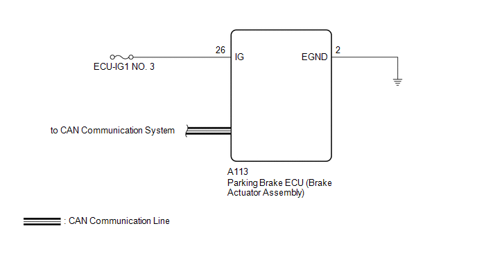
When the power switch is turned on (IG), power is supplied to the parking brake ECU (brake actuator assembly). This DTC is stored if IG power source voltage is not supplied to the parking brake ECU (brake actuator assembly) when communication with other ECUs is established.
|
DTC No. |
Detection Item |
DTC Detection Condition |
Trouble Area |
Memory |
Note |
|---|---|---|---|---|---|
|
C13A2 |
Engine Switch/Power Switch Malfunction |
Both of following conditions are met:
|
|
DTC stored |
An electric parking brake system malfunction is displayed on the multi-information display. |
WIRING DIAGRAM
CAUTION / NOTICE / HINT
NOTICE:
- Inspect the fuses for circuits related to this system before performing the following procedure.
- The electric parking brake may still operate up to 20 seconds after the power switch is turned off. Before disconnecting connectors or fuses, turn the power switch off and wait 20 seconds or more.
- After replacing the parking brake ECU (brake actuator assembly), the parking brake indicator light (red) blinks when the power switch is turned on (IG) for the first time. To turn off the parking brake indicator light (red) after replacing the parking brake ECU (brake actuator assembly), operate the electric parking brake switch to the lock side then to the release side.
PROCEDURE
|
1. |
READ VALUE USING TECHSTREAM (IG SWITCH) |
(a) Turn the power switch off.
(b) Connect the Techstream to the DLC3.
(c) Turn the power switch on (IG).
(d) Turn the Techstream on.
(e) Enter the following menus: Chassis / Electric Parking Brake / Data List.
(f) Read the Data List according to the display on the Techstream.
Chassis > Electric Parking Brake > Data List
|
Tester Display |
Measurement Item |
Range |
Normal Condition |
Diagnostic Note |
|---|---|---|---|---|
|
IG Switch |
IG power source status |
OFF or ON |
OFF: IG power source voltage is not input to skid control ECU (brake booster with master cylinder assembly) ON: IG power source voltage is input to skid control ECU (brake booster with master cylinder assembly) |
- |
Chassis > Electric Parking Brake > Data List
|
Tester Display |
|---|
|
IG Switch |
| NG |

|
|

|
2. |
CHECK DTC |
(a) Clear the DTCs.
Chassis > Electric Parking Brake > Clear DTCs
(b) Turn the power switch off.
(c) Check for DTCs.
Chassis > Electric Parking Brake > Trouble Codes
|
Result |
Proceed to |
|---|---|
|
DTCs are output |
A |
|
DTCs are not output |
B |
| A |
|
| B |
|
|
3. |
CHECK HARNESS AND CONNECTOR (PARKING BRAKE ECU (BRAKE ACTUATOR ASSEMBLY) - POWER SOURCE AND BODY GROUND) |
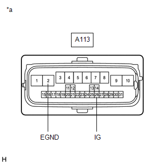
(a) Disconnect the A113 parking brake ECU (brake actuator assembly) connectors.
(b) Turn the power switch on (IG).
|
(c) Measure the voltage according to the value(s) in the table below. Standard Voltage:
|
|
(d) Turn the power switch off.
(e) Measure the resistance according to the value(s) in the table below.
Standard Resistance:
|
Tester Connection |
Condition |
Specified Condition |
|---|---|---|
|
A113-2 (EGND) - Body ground |
Always |
Below 1 Ω |
| OK |
|
REPAIR IG POWER SOURCE CIRCUIT |
| NG |
|
REPAIR OR REPLACE HARNESS OR CONNECTOR |
|
|
|