| Last Modified: 05-13-2024 | 6.11:8.1.0 | Doc ID: RM100000001G7AZ |
| Model Year Start: 2020 | Model: Corolla | Prod Date Range: [01/2019 - 09/2022] |
| Title: BRAKE CONTROL / DYNAMIC CONTROL SYSTEMS: ELECTRONICALLY CONTROLLED BRAKE SYSTEM (for HV Model): C1380; Stop Light Control Relay Malfunction; 2020 - 2022 MY Corolla Corolla HV [01/2019 - 09/2022] | ||
|
DTC |
C1380 |
Stop Light Control Relay Malfunction |
DESCRIPTION
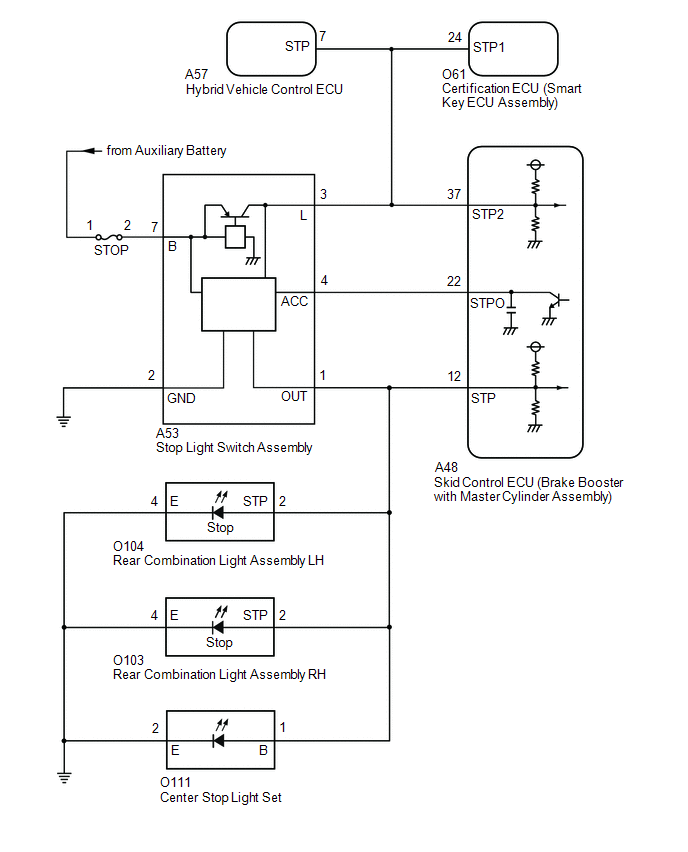
When any of the following conditions are met, the skid control ECU (brake booster with master cylinder assembly) sets the drive output (STPO) ON which operates the stop light control relay (stop light switch assembly) and turns on the stop lights.
Illumination Conditions:
- Pre-collision brake is operating.*1
- The dynamic radar cruise control system is operating and is applying the brakes.*1
- Secondary collision brake is operating.*2
- Brake hold is operating.
-
The parking brake is engaged while the vehicle is being driven.
- *1: w/ Pre-collision System
- *2: w/ Secondary Collision Brake System
|
DTC No. |
Detection Item |
INF Code |
DTC Detection Condition |
Trouble Area |
MIL |
Note |
|---|---|---|---|---|---|---|
|
C1380 |
Stop Light Control Relay Malfunction |
761 762 |
|
|
Does not come on |
VSC DTC |
WIRING DIAGRAM
CAUTION / NOTICE / HINT
NOTICE:
-
After replacing the skid control ECU (brake booster with master cylinder assembly), perform linear solenoid valve offset learning, ABS holding solenoid valve learning, yaw rate and acceleration sensor zero point calibration and system information memorization after performing "Reset Memory".
Click here
![2020 - 2022 MY Corolla Corolla HV [01/2019 - 09/2022]; BRAKE CONTROL / DYNAMIC CONTROL SYSTEMS: ELECTRONICALLY CONTROLLED BRAKE SYSTEM (for HV Model): INITIALIZATION](/t3Portal/stylegraphics/info.gif)
- Inspect the fuses for circuits related to this system before performing the following procedure.
PROCEDURE
|
1. |
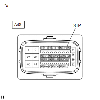
CHECK HARNESS AND CONNECTOR (STP, STPO AND STP2 TERMINAL) |
|
(a) Make sure that there is no looseness at the locking part and the connecting part of the connector. OK: The connector is securely connected. |
|
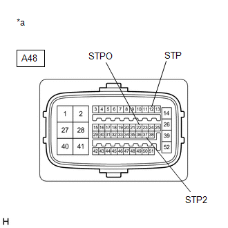
(b) Disconnect the A48 skid control ECU (brake booster with master cylinder assembly) connector.
(c) Check both the connector case and the terminals for deformation and corrosion.
OK:
No deformation or corrosion.
(d) Measure the voltage according to the value(s) in the table below.
Standard Voltage:
|
Tester Connection |
Condition |
Specified Condition |
|---|---|---|
|
A48-12 (STP) - Body ground |
Stop light switch assembly on (Brake pedal depressed) |
11 to 14 V |
|
A48-12 (STP) - Body ground |
Stop light switch assembly off (Brake pedal released) |
1.5 V or less |
|
A48-22 (STPO) - Body ground |
Always |
11 to 14 V |
|
A48-37 (STP2) - Body ground |
Stop light switch assembly on (Brake pedal depressed) |
11 to 14 V |
|
A48-37 (STP2) - Body ground |
Stop light switch assembly off (Brake pedal released) |
1.5 V or less |
|
Result |
Proceed to |
|---|---|
|
All terminal voltages are normal. |
A |
|
Only STP2 terminal voltage abnormal. |
B |
|
Only STPO terminal voltage abnormal. |
C |
|
Only STP terminal voltage abnormal. |
D |
|
STPO terminal and STP terminal voltage abnormal. |
E |
| B |

|
| C |
|
| D |
|
| E |
|
|

|
2. |
PERFORM ACTIVE TEST USING TECHSTREAM (STOP LIGHT RELAY) |
(a) Reconnect the A48 skid control ECU (brake booster with master cylinder assembly) connector.
(b) Select the Active Test on the Techstream.
Click here
Chassis > ABS/VSC/TRAC > Active Test
|
Tester Display |
Measurement Item |
Control Range |
Diagnostic Note |
|---|---|---|---|
|
Stop Light Relay |
Stop light control relay (Stop light switch assembly) |
Relay ON/OFF |
- |
Chassis > ABS/VSC/TRAC > Active Test
|
Tester Display |
|---|
|
Stop Light Relay |
(c) According to the display on the Techstream, perform the Active Test and check the operation of the stop lights.
OK:
Stop lights turn on/off in accordance with the Active Test.
| NG |
|
|
|
3. |
RECONFIRM DTC |
(a) Clear the DTCs.
Click here
Chassis > ABS/VSC/TRAC > Clear DTCs
(b) Select the Active Test on the Techstream.
Click here
Chassis > ABS/VSC/TRAC > Active Test
|
Tester Display |
Measurement Item |
Control Range |
Diagnostic Note |
|---|---|---|---|
|
Stop Light Relay |
Stop light control relay (Stop light switch assembly) |
Relay ON/OFF |
- |
Chassis > ABS/VSC/TRAC > Active Test
|
Tester Display |
|---|
|
Stop Light Relay |
(c) According to the display on the Techstream, perform the Active Test.
(d) Check if the same DTC is output.
Click here
Chassis > ABS/VSC/TRAC > Trouble Codes
|
Result |
Proceed to |
|---|---|
|
DTC C1380 is output. |
A |
|
DTC C1380 is not output. |
B |
| A |
|
| B |
|
|
4. |
INSPECT BRAKE BOOSTER WITH MASTER CYLINDER ASSEMBLY |
(a) Select the Active Test on the Techstream.
Click here
Chassis > ABS/VSC/TRAC > Active Test
|
Tester Display |
Measurement Item |
Control Range |
Diagnostic Note |
|---|---|---|---|
|
Stop Light Relay |
Stop light control relay (Stop light switch assembly) |
Relay ON/OFF |
- |
Chassis > ABS/VSC/TRAC > Active Test
|
Tester Display |
|---|
|
Stop Light Relay |
|
(b) Measure the voltage according to the value(s) in the table below. Standard Voltage:
|
|
| OK |
|
| NG |
|
|
5. |
CHECK HARNESS AND CONNECTOR (BRAKE BOOSTER WITH MASTER CYLINDER ASSEMBLY - HYBRID VEHICLE CONTROL ECU) |
|
(a) Make sure that there is no looseness at the locking part and the connecting part of the connector. OK: The connector is securely connected. |
|
(b) Disconnect the A57 hybrid vehicle control ECU connector.
(c) Check both the connector case and the terminals for deformation and corrosion.
OK:
No deformation or corrosion.
(d) Measure the voltage according to the value(s) in the table below.
Standard Voltage:
|
Tester Connection |
Condition |
Specified Condition |
|---|---|---|
|
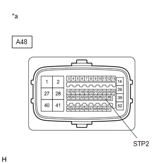
A48-37 (STP2) - Body ground |
Stop light switch assembly on (Brake pedal depressed) |
11 to 14 V |
|
A48-37 (STP2) - Body ground |
Stop light switch assembly off (Brake pedal released) |
1.5 V or less |
| OK |
|
REPLACE HYBRID VEHICLE CONTROL ECU
|
|
|
6. |
CHECK HARNESS AND CONNECTOR (BRAKE BOOSTER WITH MASTER CYLINDER ASSEMBLY - SMART KEY ECU ASSEMBLY) |
|
(a) Make sure that there is no looseness at the locking part and the connecting part of the connector. OK: The connector is securely connected. |
|
(b) Disconnect the O61 certification ECU (smart key ECU assembly) connector.
(c) Check both the connector case and the terminals for deformation and corrosion.
OK:
No deformation or corrosion.
(d) Measure the voltage according to the value(s) in the table below.
Standard Voltage:
|
Tester Connection |
Condition |
Specified Condition |
|---|---|---|
|
A48-37 (STP2) - Body ground |
Stop light switch assembly on (Brake pedal depressed) |
11 to 14 V |
|
A48-37 (STP2) - Body ground |
Stop light switch assembly off (Brake pedal released) |
1.5 V or less |
| OK |
|
REPLACE SMART KEY ECU ASSEMBLY
|
|
|
7. |
CHECK HARNESS AND CONNECTOR (BRAKE BOOSTER WITH MASTER CYLINDER ASSEMBLY - STOP LIGHT SWITCH ASSEMBLY) |
|
(a) Make sure that there is no looseness at the locking part and the connecting part of the connector. OK: The connector is securely connected. |
|
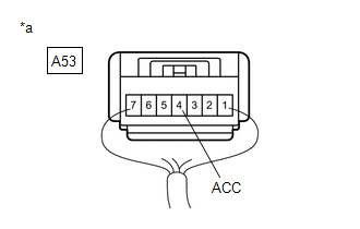
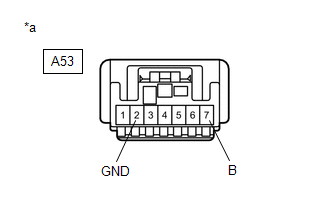
(b) Disconnect the A53 stop light switch assembly connector.
(c) Check both the connector case and the terminals for deformation and corrosion.
OK:
No deformation or corrosion.
(d) Measure the voltage according to the value(s) in the table below.
Standard Voltage:
|
Tester Connection |
Condition |
Specified Condition |
|---|---|---|
|
A48-37 (STP2) - Body ground |
Always |
1.5 V or less |
| NG |
|
REPAIR OR REPLACE HARNESS OR CONNECTOR |
|
|
8. |
CHECK HARNESS AND CONNECTOR (BRAKE BOOSTER WITH MASTER CYLINDER ASSEMBLY - STOP LIGHT SWITCH ASSEMBLY) |
(a) Measure the resistance according to the value(s) in the table below.
Standard Resistance:
|
Tester Connection |
Condition |
Specified Condition |
|---|---|---|
|
A48-37 (STP2) - A53-3 (L) |
Always |
Below 1 Ω |
|
A48-37 (STP2) or A53-3 (L) - Body ground |
Always |
10 kΩ or higher |
| OK |
|
| NG |
|
REPAIR OR REPLACE HARNESS OR CONNECTOR |
|
9. |
CHECK HARNESS AND CONNECTOR (BRAKE BOOSTER WITH MASTER CYLINDER ASSEMBLY - STOP LIGHT SWITCH ASSEMBLY) |
(a) Make sure that there is no looseness at the locking part and the connecting part of the connector.
OK:
The connector is securely connected.
(b) Disconnect the A53 stop light switch assembly connector.
(c) Check both the connector case and the terminals for deformation and corrosion.
OK:
No deformation or corrosion.
(d) Measure the resistance according to the value(s) in the table below.
Standard Resistance:
|
Tester Connection |
Condition |
Specified Condition |
|---|---|---|
|
A48-22 (STPO) - A53-4 (ACC) |
Always |
Below 1 Ω |
| OK |
|
| NG |
|
REPAIR OR REPLACE HARNESS OR CONNECTOR |
|
10. |
CHECK HARNESS AND CONNECTOR (BRAKE BOOSTER WITH MASTER CYLINDER ASSEMBLY - REAR COMBINATION LIGHT ASSEMBLY LH) |
|
(a) Make sure that there is no looseness at the locking part and the connecting part of the connector. OK: The connector is securely connected. |
|
(b) Disconnect the O104 rear combination light assembly LH connector.
(c) Check both the connector case and the terminals for deformation and corrosion.
OK:
No deformation or corrosion.
(d) Measure the voltage according to the value(s) in the table below.
Standard Voltage:
|
Tester Connection |
Condition |
Specified Condition |
|---|---|---|
|
A48-12 (STP) - Body ground |
Stop light switch assembly on (Brake pedal depressed) |
11 to 14 V |
|
A48-12 (STP) - Body ground |
Stop light switch assembly off (Brake pedal released) |
1.5 V or less |
| OK |
|
GO TO LIGHTING SYSTEM (REAR COMBINATION LIGHT ASSEMBLY LH (STOP LIGHT CIRCUIT)) Refer to "Left or right stop light does not illuminate" of problem symptoms table. Click here
|
|
|
11. |
CHECK HARNESS AND CONNECTOR (BRAKE BOOSTER WITH MASTER CYLINDER ASSEMBLY - REAR COMBINATION LIGHT ASSEMBLY RH) |
|
(a) Make sure that there is no looseness at the locking part and the connecting part of the connector. OK: The connector is securely connected. |
|
(b) Disconnect the O103 rear combination light assembly RH connector.
(c) Check both the connector case and the terminals for deformation and corrosion.
OK:
No deformation or corrosion.
(d) Measure the voltage according to the value(s) in the table below.
Standard Voltage:
|
Tester Connection |
Condition |
Specified Condition |
|---|---|---|
|
A48-12 (STP) - Body ground |
Stop light switch assembly on (Brake pedal depressed) |
11 to 14 V |
|
A48-12 (STP) - Body ground |
Stop light switch assembly off (Brake pedal released) |
1.5 V or less |
| OK |
|
GO TO LIGHTING SYSTEM (REAR COMBINATION LIGHT ASSEMBLY RH (STOP LIGHT CIRCUIT)) Refer to "Left or right stop light does not illuminate" of problem symptoms table. Click here
|
|
|
12. |
CHECK HARNESS AND CONNECTOR (BRAKE BOOSTER WITH MASTER CYLINDER ASSEMBLY - CENTER STOP LIGHT SET) |
|
(a) Make sure that there is no looseness at the locking part and the connecting part of the connector. OK: The connector is securely connected. |
|
(b) Disconnect the O111 center stop light set connector.
(c) Check both the connector case and the terminals for deformation and corrosion.
OK:
No deformation or corrosion.
(d) Measure the voltage according to the value(s) in the table below.
Standard Voltage:
|
Tester Connection |
Condition |
Specified Condition |
|---|---|---|
|
A48-12 (STP) - Body ground |
Stop light switch assembly on (Brake pedal depressed) |
11 to 14 V |
|
A48-12 (STP) - Body ground |
Stop light switch assembly off (Brake pedal released) |
1.5 V or less |
| OK |
|
|
|
13. |
CHECK HARNESS AND CONNECTOR (BRAKE BOOSTER WITH MASTER CYLINDER ASSEMBLY - STOP LIGHT SWITCH ASSEMBLY) |
|
(a) Make sure that there is no looseness at the locking part and the connecting part of the connector. OK: The connector is securely connected. |
|
(b) Disconnect the A53 stop light switch assembly connector.
(c) Check both the connector case and the terminals for deformation and corrosion.
OK:
No deformation or corrosion.
(d) Measure the voltage according to the value(s) in the table below.
Standard Voltage:
|
Tester Connection |
Condition |
Specified Condition |
|---|---|---|
|
A48-12 (STP) - Body ground |
Always |
1.5 V or less |
| NG |
|
REPAIR OR REPLACE HARNESS OR CONNECTOR |
|
|
14. |
CHECK HARNESS AND CONNECTOR (BRAKE BOOSTER WITH MASTER CYLINDER ASSEMBLY - STOP LIGHT SWITCH ASSEMBLY) |
(a) Measure the resistance according to the value(s) in the table below.
Standard Resistance:
|
Tester Connection |
Condition |
Specified Condition |
|---|---|---|
|
A53-1 (OUT) - A48-12 (STP) |
Always |
Below 1 Ω |
|
A53-1 (OUT) or A48-12 (STP) - Body ground |
Always |
10 kΩ or higher |
| OK |
|
| NG |
|
REPAIR OR REPLACE HARNESS OR CONNECTOR |
|
15. |
CHECK STOP LIGHT SWITCH ASSEMBLY POWER SOURCE CIRCUIT |
|
(a) Make sure that there is no looseness at the locking part and the connecting part of the connector. OK: The connector is securely connected. |
|
(b) Disconnect the A53 stop light switch assembly connector.
(c) Check both the connector case and the terminals for deformation and corrosion.
OK:
No deformation or corrosion.
(d) Measure the voltage according to the value(s) in the table below.
Standard Voltage:
|
Tester Connection |
Condition |
Specified Condition |
|---|---|---|
|
A53-7 (B) - Body ground |
Always |
11 to 14 V |
(e) Measure the resistance according to the value(s) in the table below.
Standard Resistance:
|
Tester Connection |
Condition |
Specified Condition |
|---|---|---|
|
A53-2 (GND) - Body ground |
1 minute or more after disconnecting the cable from the negative (-) auxiliary battery terminal |
Below 1 Ω |
| NG |
|
REPAIR OR REPLACE HARNESS OR CONNECTOR |
|
|
16. |
CHECK HARNESS AND CONNECTOR (BRAKE BOOSTER WITH MASTER CYLINDER ASSEMBLY - STOP LIGHT SWITCH ASSEMBLY) |
(a) Measure the resistance according to the value(s) in the table below.
Standard Resistance:
|
Tester Connection |
Condition |
Specified Condition |
|---|---|---|
|
A48-22 (STPO) or A53-4 (ACC) - Body ground |
Always |
10 kΩ or higher |
| OK |
|
| NG |
|
REPAIR OR REPLACE HARNESS OR CONNECTOR |
|
|
|