| Last Modified: 05-13-2024 | 6.11:8.1.0 | Doc ID: RM100000001G45S |
| Model Year Start: 2020 | Model: Corolla | Prod Date Range: [01/2019 - 03/2019] |
| Title: 2ZR-FAE (ENGINE MECHANICAL): ENGINE UNIT: REASSEMBLY; 2020 MY Corolla [01/2019 - 03/2019] | ||
REASSEMBLY
CAUTION / NOTICE / HINT
HINT:
Perform "Inspection After Repair" after replacing the camshaft, No. 2 camshaft, camshaft timing gear assembly, camshaft timing exhaust gear assembly or engine coolant temperature sensor.
Click here
![2020 - 2023 MY Corolla [01/2019 - 11/2022]; 2ZR-FAE (ENGINE CONTROL): SFI SYSTEM: INITIALIZATION](/t3Portal/stylegraphics/info.gif)
PROCEDURE
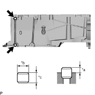
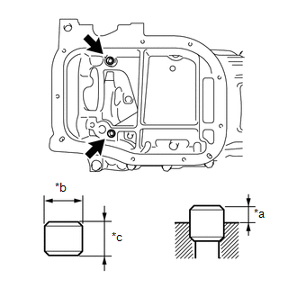
1. INSTALL STIFFENING CRANKCASE RING PIN
NOTICE:
It is not necessary to remove ring pins unless they are being replaced.
|
(a) Using a plastic hammer, tap 2 new ring pins into the stiffening crankcase assembly. Standard Ring Pin:
|
|
|
(b) Using a plastic-faced hammer, tap in 2 new stiffening crankcase ring pins until they are seated. Standard Ring Pin:
|
|
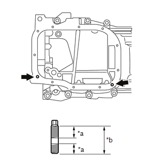
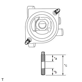
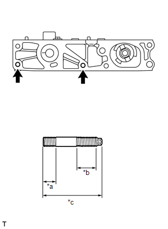
2. INSTALL STUD BOLT
NOTICE:
If a stud bolt is deformed or the threads are damaged, replace it.
|
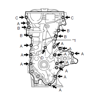
(a) Using an E6 "TORX" socket wrench, install the stiffening crankcase stud bolts as shown in the illustration. Torque: 5.0 N·m {51 kgf·cm, 44 in·lbf} |
|
|
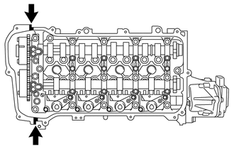
(b) Using an E5 "TORX" socket wrench, install the 2 water inlet housing stud bolts as shown in the illustration. Torque: 5.0 N·m {51 kgf·cm, 44 in·lbf} |
|
|
(c) Using an E7 "TORX" socket wrench, install the camshaft housing stud bolts. Torque: 9.5 N·m {97 kgf·cm, 84 in·lbf} |
|
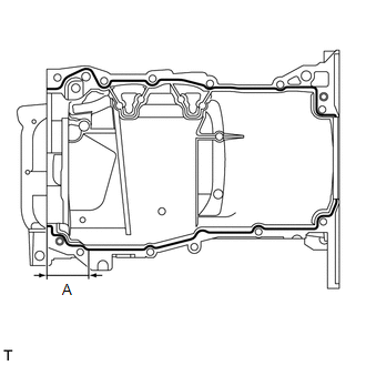
3. INSTALL STIFFENING CRANKCASE ASSEMBLY
|
(a) Apply seal packing as shown in the illustration. Seal Packing: Toyota Genuine Seal Packing Black, Three Bond 1207B or equivalent Standard Seal Diameter:
Application Length (A): 56 mm (2.20 in.) NOTICE:
|
|
|
(b) Install the stiffening crankcase assembly with the 11 bolts in the order shown in the illustration. Torque: 21 N·m {214 kgf·cm, 15 ft·lbf} Bolt Length:
|
|
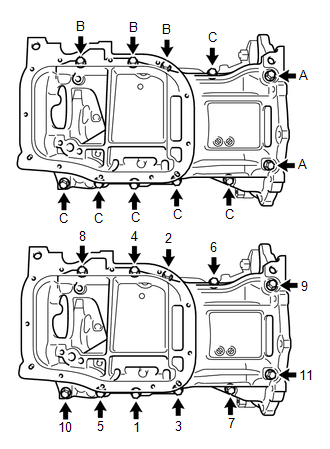
(c) Recheck the torque for the bolts (1) and (2).
Torque:
21 N·m {214 kgf·cm, 15 ft·lbf}
(d) Wipe off any excess seal packing with a clean piece of cloth.
4. INSTALL OIL PUMP ASSEMBLY
Click here
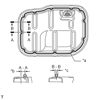
5. INSTALL NO. 2 OIL PAN SUB-ASSEMBLY
(a) Remove any remaining seal packing.
NOTICE:
- Remove any oil from the contact surfaces.
- Install the No. 2 oil pan sub-assembly within 3 minutes and tighten the bolts within 10 minutes of applying seal packing.
- Tighten the bolts and nuts within 15 minutes of applying seal packing.
- Do not add engine oil for at least 2 hours after installation.
|
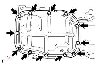
(b) Apply seal packing in a continuous line as shown in the illustration. Seal Packing: Toyota Genuine Seal Packing Black, Three Bond 1207B or equivalent Application Specification:
|
|
|
(c) Install the No. 2 oil pan sub-assembly to the stiffening crankcase assembly with the 10 bolts and 2 nuts. Torque: 10 N·m {102 kgf·cm, 7 ft·lbf} |
|
6. INSTALL OIL PAN DRAIN PLUG
(a) Install a new gasket and oil pan drain plug to the No. 2 oil pan sub-assembly.
Torque:
37 N·m {377 kgf·cm, 27 ft·lbf}
7. INSTALL REAR ENGINE OIL SEAL
Click here
8. INSTALL NO. 1 TAPER SCREW PLUG
(a) Apply adhesive to 2 or 3 threads of the No. 1 taper screw plug, and install the No. 1 taper screw plug.
Torque:
43 N·m {438 kgf·cm, 32 ft·lbf}
Adhesive:
Toyota Genuine Adhesive 1324, Three Bond 1324 or equivalent
NOTICE:
- Install the No. 1 taper screw plug within 3 minutes of applying adhesive.
- Do not start the engine for at least 1 hour after installing the No. 1 taper screw plug.
9. INSTALL PCV VALVE (VENTILATION VALVE SUB-ASSEMBLY)
Click here
10. INSTALL CYLINDER HEAD GASKET
Click here
11. INSTALL CYLINDER HEAD SUB-ASSEMBLY
Click here
12. INSTALL VALVE LASH ADJUSTER ASSEMBLY
(a) Inspect the 16 valve lash adjuster assemblies before installing them.
Click here
(b) Install the 16 valve lash adjuster assemblies to the cylinder head sub-assembly.
NOTICE:
Install each part to its original location.
13. INSTALL VALVE STEM CAP
(a) Apply a light coat of engine oil to the valve stem caps.
(b) Install the 16 valve stem caps.
HINT:
Do not drop the valve stem caps into the cylinder head sub-assembly.
14. INSTALL NO. 1 VALVE ROCKER ARM SUB-ASSEMBLY
|
(a) Apply engine oil to the tips of the valve lash adjuster assemblies and valve stem caps. |
|
(b) Install the 16 No. 1 valve rocker arm sub-assemblies as shown in the illustration.
NOTICE:
Install each part to its original location.
15. INSTALL CAMSHAFT HOUSING STRAIGHT PIN
NOTICE:
It is not necessary to remove a camshaft housing straight pin unless it is being replaced.
|
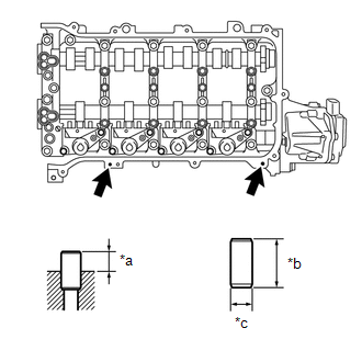
(a) Using a plastic-faced hammer, tap in 2 new camshaft housing straight pin to the specified protrusion height. Standard Straight Pin:
|
|
16. INSTALL CONTINUOUSLY VARIABLE VALVE LIFT CONTROLLER ASSEMBLY
Click here
17. INSTALL CAMSHAFT HOUSING SUB-ASSEMBLY
Click here
18. INSTALL CAMSHAFT TIMING EXHAUST GEAR ASSEMBLY
|
(a) Fit the camshaft timing exhaust gear assembly and camshaft together by aligning the pin hole and straight pin. NOTICE: Do not forcibly push in the camshaft timing exhaust gear assembly. This may cause the straight pin tip to damage the installation surface of the camshaft timing exhaust gear assembly. |
|
(b) Lightly press the camshaft timing exhaust gear assembly against the camshaft and turn the camshaft timing exhaust gear assembly. Push further at the position where the pin enters the hole.
NOTICE:
Be sure not to turn the camshaft timing exhaust gear assembly in the retard direction (clockwise).
|
(c) Check that there is no clearance between the camshaft timing exhaust gear assembly and camshaft flange. |
|

|
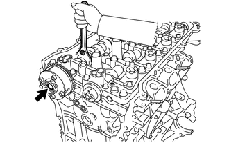
(d) Tighten the bolt with the camshaft timing exhaust gear assembly secured in place. Torque: 54 N·m {551 kgf·cm, 40 ft·lbf} |
|
(e) Check the camshaft timing exhaust gear assembly lock.
(1) Make sure that the camshaft timing exhaust gear assembly is locked.
HINT:
Perform "Inspection After Repair" after replacing the camshaft timing exhaust gear assembly.
Click here
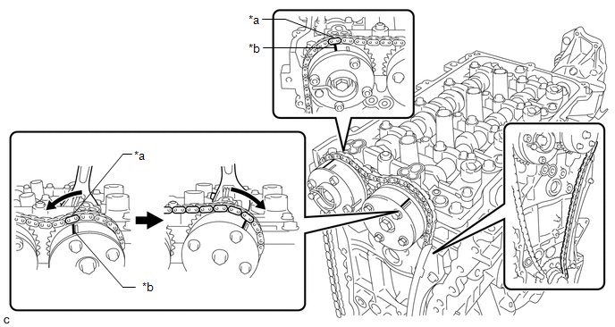
19. INSTALL CAMSHAFT TIMING GEAR ASSEMBLY
|
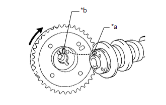
(a) Put the camshaft timing gear assembly and camshaft together with the straight pin and key groove misaligned as shown in the illustration. NOTICE: Do not forcibly push in the camshaft timing gear assembly. This may cause the straight pin tip to damage the installation surface of the camshaft timing gear assembly. |
|
|
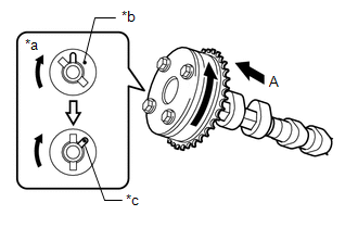
(b) Turn the camshaft timing gear assembly as shown in the illustration while pushing it gently against the camshaft. Push further at the position where the pin fits into the groove. NOTICE: Do not turn the camshaft timing gear assembly in the retard direction (clockwise). |
|
|
(c) Check that there is no clearance between the camshaft timing gear assembly and camshaft flange. |
|
|
(d) Tighten the bolt with the camshaft timing gear assembly secured in place. Torque: 54 N·m {551 kgf·cm, 40 ft·lbf} |
|
(e) Check that the camshaft timing gear assembly can move in the retard direction (clockwise) and is locked in the most retarded position.
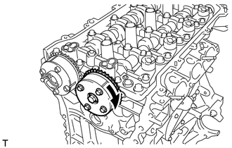

|
Lock |
HINT:
Perform "Inspection After Repair" after replacing the camshaft timing gear assembly.
Click here
20. INSTALL CRANKSHAFT TIMING GEAR KEY
(a) Using a plastic hammer, tap in the 2 crankshaft timing gear keys.
HINT:
Tap in the crankshaft timing gear keys until they contact the crankshaft as shown in the illustration.
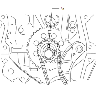
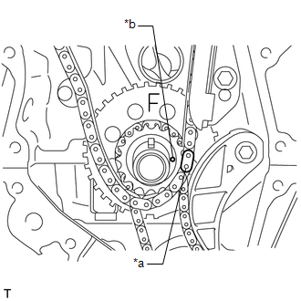
21. INSTALL NO. 1 CRANKSHAFT POSITION SENSOR PLATE
|
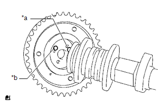
(a) Install the No. 1 crankshaft position sensor plate to the crankshaft with the "F" mark facing forward. |
|
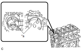
22. INSTALL NO. 2 CHAIN SUB-ASSEMBLY
(a) Temporarily install the crankshaft pulley set bolt to the crankshaft.
|
(b) Set the crankshaft timing gear keys as shown in the illustration. |
|
(c) Turn the oil pump drive shaft so that the flat face is facing upward.
(d) Remove the crankshaft pulley set bolt from the crankshaft.
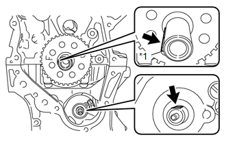
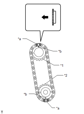
(e) Align the mark plates (yellow) with the timing mark of the oil pump drive gear and oil pump drive shaft gear as shown in the illustration.
|
*1 |
Oil Pump Drive Gear |
|
*2 |
Oil Pump Drive Shaft Gear |
|
*a |
Mark Plate (Yellow) |
|
*b |
Timing Mark |
|
|
Front of Engine |
HINT:
Make sure the mark plates (yellow) of the No. 2 chain sub-assembly are facing away from the engine assembly.
(f) With the No. 2 chain sub-assembly placed around the oil pump drive gear and oil pump drive shaft gear, install the oil pump drive gear to the crankshaft and temporarily install the oil pump drive shaft gear to the oil pump drive shaft.
(g) Temporarily install the oil pump drive shaft gear nut.
(h) Install the chain damper spring to the chain tensioner plate, and then install the chain tensioner plate with the bolt.
Torque:
10 N·m {102 kgf·cm, 7 ft·lbf}
|
(i) Temporarily install the crankshaft pulley with the crankshaft pulley set bolt. |
|
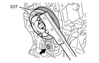
(j) Using SST, hold the crankshaft pulley. Then tighten the oil pump drive shaft gear nut.
SST: 09213-54015
91551-00850
SST: 09330-00021
Torque:
28 N·m {286 kgf·cm, 21 ft·lbf}
(k) Remove SST, the crankshaft pulley set bolt and crankshaft pulley.
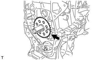
23. INSTALL CRANKSHAFT TIMING SPROCKET
(a) Install the crankshaft timing sprocket to the crankshaft as shown in the illustration.
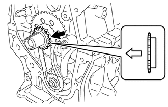

|
Front of Engine |
24. INSTALL NO. 1 CHAIN VIBRATION DAMPER
(a) Install the No. 1 chain vibration damper with the 2 bolts.
Torque:
21 N·m {214 kgf·cm, 15 ft·lbf}
25. SET NO. 1 CYLINDER TO TDC/COMPRESSION
(a) Temporarily install the crankshaft pulley set bolt.
|
(b) Turn the crankshaft counterclockwise to position the timing gear key to the top. |
|
|
(c) Check that the timing marks on the camshaft timing exhaust gear assembly and camshaft timing gear assembly are aligned as shown in the illustration. |
|
(d) Remove the crankshaft pulley set bolt.
26. INSTALL CHAIN SUB-ASSEMBLY
(a) Align the mark plates (orange) with the timing marks as shown in the illustration and install the chain sub-assembly.
|
*a |
Mark Plate (Orange) |
*b |
Timing Mark |
HINT:
- Be sure to position the mark plate at the front of the engine.
- The mark plate on the camshaft side is colored orange.
- Do not pass the chain sub-assembly around the sprocket of the camshaft timing gear assembly. Only place it on the sprocket.
- Pass the chain sub-assembly through the No. 1 chain vibration damper.
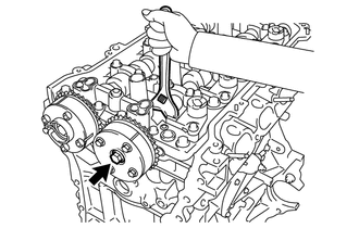
(b) Hold the hexagonal portion of the camshaft with a wrench and turn the camshaft timing gear assembly counterclockwise to align the mark plate (orange) and timing mark, and then install the chain sub-assembly.
(c) Hold the hexagonal portion of the camshaft with a wrench and turn the camshaft timing gear assembly clockwise.
HINT:
To tension the chain sub-assembly, slowly turn the camshaft timing gear assembly clockwise to prevent the chain sub-assembly from being misaligned.
|
(d) Align the mark plate (yellow) and timing mark and install the chain sub-assembly to the crankshaft timing sprocket. HINT: The mark plate on the crankshaft side is colored yellow. |
|
27. INSTALL CHAIN TENSIONER SLIPPER
(a) Install the chain tensioner slipper to the cylinder block sub-assembly.
28. CHECK NO. 1 CYLINDER IS TDC/COMPRESSION
(a) Check each timing mark at TDC/compression.
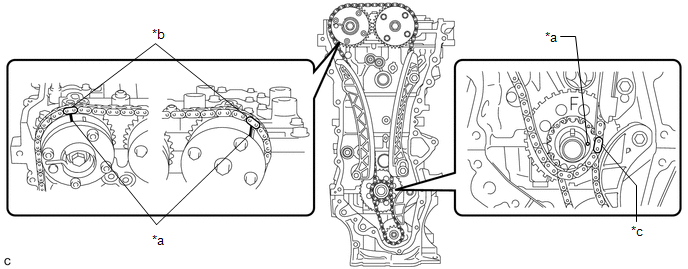
|
*a |
Timing Mark |
*b |
Mark Plate (Orange) |
|
*c |
Mark Plate (Yellow) |
- |
- |
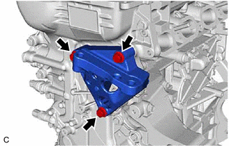
29. INSTALL NO. 1 GENERATOR BRACKET
(a) Install the No. 1 generator bracket to the cylinder block sub-assembly with the 4 bolts.
Torque:
24 N·m {245 kgf·cm, 18 ft·lbf}
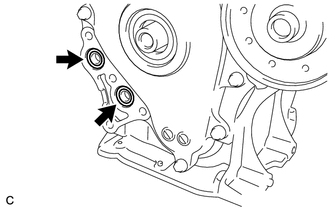
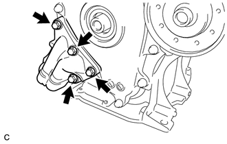
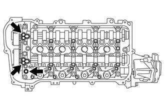
30. INSTALL WATER INLET HOUSING
(a) Install a new gasket and water inlet housing to the timing chain cover sub-assembly with the 3 bolts.
Torque:
10 N·m {102 kgf·cm, 7 ft·lbf}
31. INSTALL TIMING CHAIN COVER SUB-ASSEMBLY
(a) Install a new gasket to the timing chain cover sub-assembly.
NOTICE:
Remove any oil from the contact surface.
(b) Install the engine water pump assembly to the timing chain cover sub-assembly with the 3 bolts.
Torque:
21 N·m {214 kgf·cm, 15 ft·lbf}
(c) Remove any remaining seal packing material.
(d) Clean the contact surfaces of the timing chain cover sub-assembly, camshaft housing sub-assembly, cylinder head sub-assembly, cylinder block sub-assembly and stiffening crankcase assembly, and confirm that no oil, moisture, or other foreign matter is on the surfaces.
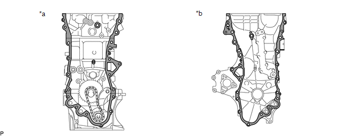
|
*a |
Engine Assembly Side |
*b |
Timing Chain Cover Sub-assembly Side |

|
Clean and degrease |
- |
- |
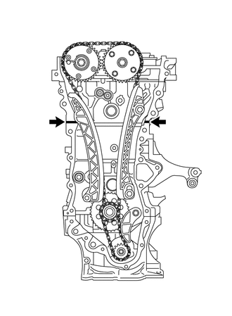
(e) Install 2 new O-rings to the cylinder head sub-assembly.
(f) Install a new O-ring to the cylinder block sub-assembly.
|
(g) Apply seal packing to the engine unit as shown in the illustration. Seal Packing: Toyota Genuine Seal Packing Black, Three Bond 1207B or equivalent Standard Seal Diameter: 5.0 mm (0.197 in.) NOTICE: Install the timing chain cover sub-assembly within 3 minutes and tighten the bolts within 10 minutes of applying seal packing. |
|
(h) Apply seal packing in a continuous line to the timing chain cover sub-assembly as shown in the following illustration.
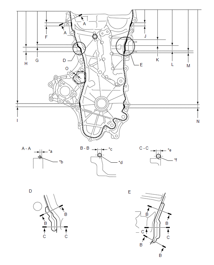
|
*a |
2.5 mm (0.10 in.) |
*b |
2.5 to 3.5 mm (0.10 to 0.14 in.) |
|
*c |
5.0 mm (0.20 in.) |
*d |
4.5 to 5.5 mm (0.18 to 0.22 in.) |
|
*e |
7.5 mm (0.30 in.) |
*f |
7.0 to 8.0 mm (0.28 to 0.31 in.) |
Seal Packing:
|
Item |
Seal Packing |
|---|---|
|
Dashed line |
Toyota Genuine Seal Packing Black, Three Bond 1207B or equivalent |
|
Continuous line |
|
|
Alternate long and short dashed line |
Toyota Genuine Seal Packing 1282B, Three Bond 1282B or equivalent |
Application Specification:
|
Area |
Seal Packing Diameter |
Distance from Edge of Cover to: |
Seal Packing Application Length |
Distance from Top of Cover to Top of Seal Packing |
|---|---|---|---|---|
|
Dashed line |
2.5 to 3.5 mm (0.0984 to 0.138 in.) |
Center of seal packing 2.5 mm (0.0984 in.) |
- |
- |
|
Continuous line |
4.5 to 5.5 mm (0.177 to 0.217 in.) or 7.0 to 8.0 mm (0.276 to 0.315 in.) |
- |
- |
- |
|
Alternate long and short dashed line |
4.0 mm (0.157 in.) |
Center of seal packing 3.0 mm (0.118 in.) |
- |
- |
|
(A) - (A) |
2.5 to 3.5 mm (0.0984 to 0.138 in.) |
Center of seal packing 2.5 mm (0.0984 in.) |
- |
- |
|
(B) - (B) |
4.5 to 5.5 mm (0.177 to 0.217 in.) |
Opposite edge of seal packing 5.0 mm (0.197 in.) |
- |
- |
|
(C) - (C) |
7.0 to 8.0 mm (0.276 to 0.315 in.) |
Opposite edge of seal packing 7.5 mm (0.295 in.) |
- |
- |
|
(F) |
4.5 to 5.5 mm (0.177 to 0.217 in.) |
- |
15.8 mm (0.622 in.) |
50.1 mm (1.97 in.) |
|
(G) |
4.5 to 5.5 mm (0.177 to 0.217 in.) |
- |
10.3 mm (0.406 in.) |
155.1 mm (6.11 in.) |
|
(H) |
7.0 to 8.0 mm (0.276 to 0.315 in.) |
- |
19.5 mm (0.768 in.) |
165.4 mm (6.51 in.) |
|
(I) |
4.5 to 5.5 mm (0.177 to 0.217 in.) |
- |
14.6 mm (0.575 in.) |
397.8 mm (15.7 in.) |
|
(J) |
4.5 to 5.5 mm (0.177 to 0.217 in.) |
- |
18.6 mm (0.732 in.) |
51.4 mm (2.02 in.) |
|
(K) |
4.5 to 5.5 mm (0.177 to 0.217 in.) |
- |
25.3 mm (0.996 in.) |
133.9 mm (5.27 in.) |
|
(L) |
7.0 to 8.0 mm (0.276 to 0.315 in.) |
- |
25.8 mm (1.02 in.) |
159.2 mm (6.27 in.) |
|
(M) |
4.5 to 5.5 mm (0.177 to 0.217 in.) |
- |
5.0 mm (0.197 in.) |
185.0 mm (7.28 in.) |
|
(N) |
4.5 to 5.5 mm (0.177 to 0.217 in.) |
- |
14.6 mm (0.575 in.) |
397.8 mm (15.7 in.) |
|
(O) |
4.0 mm (0.157 in.) |
Center of seal packing 3.0 mm (0.118 in.) |
- |
- |
NOTICE:
Install the timing chain cover sub-assembly within 3 minutes and tighten the bolts within 10 minutes of applying seal packing.
(i) Clean the bolts and their installation holes.
|
(j) Apply adhesive to 5 and a half threads or more of the end of the bolt (C). Adhesive: Toyota Genuine Adhesive 1324, Three Bond 1324 or equivalent |
|
|
(k) Temporarily install the timing chain cover sub-assembly with the 19 bolts and a new seal washer. Bolt Length:
NOTICE: Make sure that there is no oil on the threads of the bolts. |
|
|
(l) Temporarily install the engine mounting bracket RH to the timing chain cover sub-assembly with the 3 bolts. Bolt Length:
NOTICE: Make sure that there is no oil on the threads of the bolts. |
|
|
(m) Install 2 new O-rings to the timing chain cover sub-assembly. |
|
|
(n) Temporarily install the oil filter bracket to the timing chain cover sub-assembly with the 4 bolts. Bolt Length:
NOTICE: Make sure that there is no oil on the threads of the bolts. |
|
(o) Install the timing chain cover sub-assembly with the 26 bolts and a new seal washer in the order shown in the illustration.
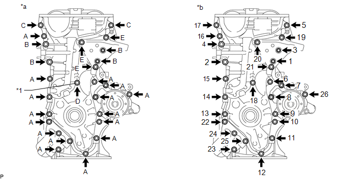
|
*1 |
Seal Washer |
- |
- |
|
*a |
Torque |
*b |
Bolt Tightening Order |
Torque:
Bolt (A), (C) :
25.5 N·m {260 kgf·cm, 19 ft·lbf}
Bolt (B), (E) :
51 N·m {520 kgf·cm, 38 ft·lbf}
Bolt (D) :
10 N·m {102 kgf·cm, 7 ft·lbf}
NOTICE:
- Install the timing chain cover sub-assembly within 3 minutes and tighten the bolts within 10 minutes of applying seal packing.
- Do not start the engine for at least 2 hours after installation.
- Make sure that there is no oil on the threads of the bolts.
32. INSTALL TIMING CHAIN COVER OIL SEAL
Click here
33. INSTALL CRANKSHAFT PULLEY
Click here
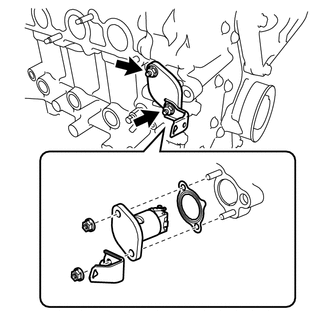
34. INSTALL NO. 1 CHAIN TENSIONER ASSEMBLY
|
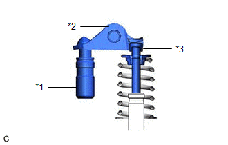
(a) Raise the cam, then fully push in the plunger and engage the hook to the pin so that the plunger is in the position shown in the illustration. NOTICE: Make sure that the cam engages with the first tooth of the plunger to allow the hook to pass over the pin. |
|
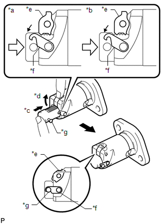
|
(b) Install a new gasket, the bracket and No. 1 chain tensioner assembly with the 2 nuts. Torque: 12 N·m {122 kgf·cm, 9 ft·lbf} NOTICE: If the hook releases the plunger while the No. 1 chain tensioner assembly is being installed, set the hook again. |
|
|
(c) Rotate the crankshaft counterclockwise slightly and check that the hook becomes released. |
|
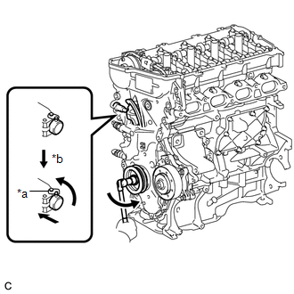
|
(d) Turn the crankshaft clockwise and check that the plunger is extended. |
|
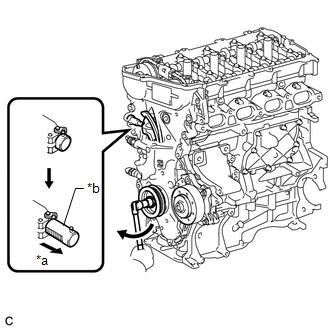
35. INSTALL OIL FILTER UNION
(a) Using a 12 mm hexagon socket wrench, install the oil filter union to the oil filter bracket.
Torque:
29.5 N·m {301 kgf·cm, 22 ft·lbf}
36. INSTALL OIL FILTER SUB-ASSEMBLY
Click here
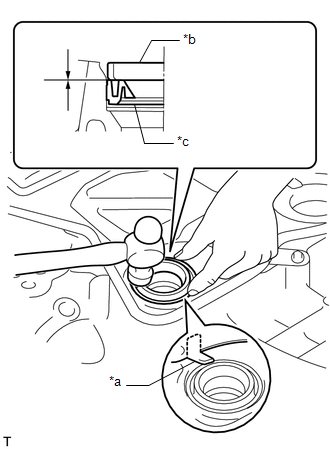
37. INSTALL SPARK PLUG TUBE GASKET
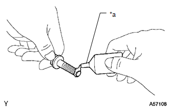
|
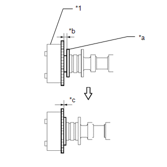
(a) Using a hammer and the spark plug tube gasket which has had the sealing part cut off, uniformly tap in a new spark plug tube gasket all the way. NOTICE:
HINT: If a spark plug tube gasket that will be used to install the spark plug tube gasket is deformed, and cannot be positioned on the spark plug tube gasket, correct the deformation using pliers. |
|
(b) Return the 4 claws of the ventilation baffle plate to their original positions.
38. INSTALL CYLINDER HEAD COVER GASKET
(a) Install a new cylinder head cover gasket to the cylinder head cover sub-assembly.
NOTICE:
Remove any oil from the contact surfaces.
39. INSTALL CYLINDER HEAD COVER SUB-ASSEMBLY
|
(a) Install 3 new gaskets to the camshaft bearing cap. |
|
|
(b) Apply seal packing as shown the illustration. Seal Packing: Toyota Genuine Seal Packing Black, Three Bond 1207B or equivalent Standard Diameter: 4.0 mm (0.157 in.) NOTICE:
|
|
|
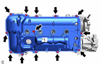
(c) Install the cylinder head cover sub-assembly to the camshaft housing sub-assembly with the 13 bolts and a new seal washer in the order shown in the illustration. Torque: 10 N·m {102 kgf·cm, 7 ft·lbf} |
|
40. INSTALL ENGINE OIL PRESSURE SWITCH ASSEMBLY
Click here
41. INSTALL ENGINE COOLANT TEMPERATURE SENSOR
Click here
42. INSTALL KNOCK CONTROL SENSOR
Click here
43. INSTALL CRANKSHAFT POSITION SENSOR
Click here
44. INSTALL CAMSHAFT TIMING OIL CONTROL VALVE ASSEMBLY
-
for Intake Side:
Click here
-
for Exhaust Side:
Click here
45. INSTALL CAMSHAFT POSITION SENSOR
Click here
46. INSTALL VALVEMATIC SHAFT SENSOR (CAM POSITION SENSOR)
Click here
47. INSTALL SPARK PLUG
Click here
48. INSTALL OIL FILLER CAP GASKET
(a) Install the oil filler cap gasket to the oil filler cap sub-assembly.
49. INSTALL OIL FILLER CAP SUB-ASSEMBLY
(a) Install the oil filler cap sub-assembly to the cylinder head cover sub-assembly.
|
|
|