- Reset memory
- Deceleration sensor zero point calibration
- CVT oil pressure calibration
| Last Modified: 01-27-2025 | 6.11:8.1.0 | Doc ID: RM100000001G45P |
| Model Year Start: 2020 | Model: Corolla | Prod Date Range: [01/2019 - 03/2019] |
| Title: 2ZR-FAE (ENGINE MECHANICAL): ENGINE UNIT: REMOVAL; 2020 MY Corolla [01/2019 - 03/2019] | ||
REMOVAL
CAUTION / NOTICE / HINT
The necessary procedures (adjustment, calibration, initialization, or registration) that must be performed after parts are removed and installed, or replaced during engine unit removal/installation are shown below.
Necessary Procedures After Parts Removed/Installed/Replaced
|
Replaced Part or Performed Procedure |
Necessary Procedure |
Effect/Inoperative Function when Necessary Procedure not Performed |
Link |
|---|---|---|---|
|
*1: w/ Smart Key System
*2: w/o Smart Key System |
|||
|
Battery terminal is disconnected/reconnected |
Perform steering sensor zero point calibration |
Lane Control System |
|
|
Pre-collision System |
|||
|
Lighting System (w/ AFS)(EXT) |
|||
|
Replacement of ECM |
Vehicle Identification Number (VIN) registration |
MIL comes on |
|
|
ECU communication ID registration (Immobiliser system) |
Engine start function |
|
|
|
|
|
|
|
|
Replacement of ECM*1 |
Code registration (Smart Key System (for Gasoline Model, Start Function)) |
|
|
|
Replacement of ECM*2 |
Code registration (Immobiliser system) |
Engine start |
|
|
Inspection After Repair |
|
|
|
Suspension, tires, etc. (The vehicle height changes because of suspension or tire replacement) |
Perform headlight ECU sub-assembly LH initialization |
Lighting system (w/ AFS)(EXT) |
|
|
Front wheel alignment adjustment |
|
|
w/ Electric Parking Brake System:
w/o Electric Parking Brake System:
|
|
CVT fluid |
ATF thermal degradation estimate reset |
The value of the Data List item "ATF Thermal Degradation Estimate" is not estimated correctly |
|
NOTICE:
- After the ignition switch is turned off, the radio and display receiver assembly records various types of memory and settings. As a result, after turning the ignition switch off, make sure to wait at least 85 seconds before disconnecting the cable from the negative (-) battery terminal. (for Audio and Visual System (for Gasoline Model))
- After the engine switch is turned off, the radio and display receiver assembly records various types of memory and settings. As a result, after turning the engine switch off, make sure to wait at least 85 seconds before disconnecting the cable from the negative (-) battery terminal. (for Navigation System)
PROCEDURE
1. REMOVE THROTTLE BODY ASSEMBLY
Click here
![2020 - 2023 MY Corolla [01/2019 - 11/2022]; 2ZR-FAE (ENGINE CONTROL): THROTTLE BODY: REMOVAL+](/t3Portal/stylegraphics/info.gif)
2. REMOVE INTAKE MANIFOLD
Click here
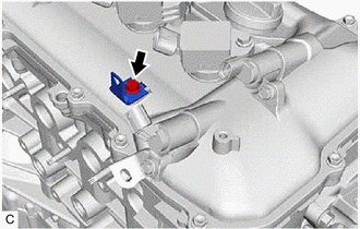
3. REMOVE PURGE VALVE (PURGE VSV)
(a) Remove the 2 bolts and purge valve (purge VSV) from the cylinder head cover sub-assembly.
4. DISCONNECT FUEL TUBE SUB-ASSEMBLY
Click here
5. REMOVE FUEL DELIVERY PIPE SUB-ASSEMBLY
Click here
6. REMOVE NO. 1 DELIVERY PIPE SPACER
Click here
7. REMOVE FUEL INJECTOR ASSEMBLY
Click here
8. REMOVE ENGINE OIL LEVEL DIPSTICK GUIDE
(a) Remove the engine oil level dipstick.
|
(b) Remove the bolt and engine oil level dipstick guide. |
|
(c) Remove the O-ring from the engine oil level dipstick guide.
9. REMOVE NO. 1 EXHAUST MANIFOLD HEAT INSULATOR
Click here
10. REMOVE DRIVE SHAFT HEAT INSULATOR SUB-ASSEMBLY
Click here
11. REMOVE MANIFOLD STAY
Click here
12. REMOVE EXHAUST MANIFOLD
Click here
13. REMOVE VENTILATION HOSE
Click here
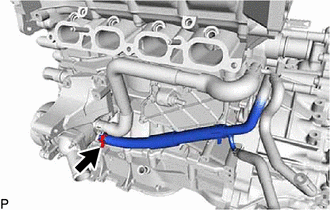
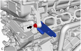
14. DISCONNECT NO. 3 WATER BY-PASS HOSE
|
(a) Slide the clip and disconnect the No. 3 water by-pass hose from the water inlet housing |
|
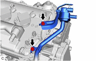
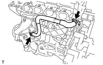
15. REMOVE NO. 1 WATER BY-PASS PIPE
|
(a) Remove the 2 bolts and No. 1 water by-pass pipe. |
|
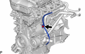
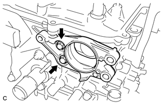
16. REMOVE WATER BY-PASS HOSE
|
(a) Slide the clip and remove the water by-pass hose from the cylinder head sub-assembly. |
|
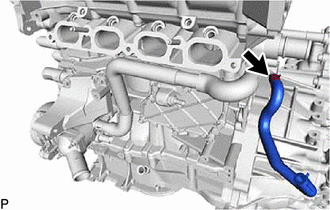
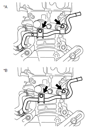
17. REMOVE WATER INLET HOSE
|
(a) Slide the 2 clips and remove the water inlet hose. |
|
18. SEPARATE WATER INLET
Click here
19. REMOVE THERMOSTAT
Click here
20. REMOVE VACUUM PUMP ASSEMBLY
Click here
21. REMOVE NO. 1 VACUUM PUMP BRACKET
|
(a) Remove the 2 bolts, No. 1 vacuum pump bracket and gasket. |
|
22. REMOVE NO. 2 GENERATOR BRACKET
|
(a) Remove the bolt and No. 2 generator bracket from the cylinder head sub-assembly. |
|
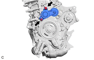
23. REMOVE V-RIBBED BELT TENSIONER ASSEMBLY
NOTICE:
Do not supply oil to the tensioner when an abnormal noise of the belt occurs.
|
(a) Remove the 2 bolts and V-ribbed belt tensioner assembly from the engine assembly. |
|
24. REMOVE WIRE HARNESS CLAMP BRACKET
|
(a) Remove the bolt and wire harness clamp bracket from the cylinder head cover sub-assembly. |
|
25. REMOVE IGNITION COIL ASSEMBLY
Click here
26. REMOVE ENGINE OIL TEMPERATURE SENSOR
Click here
|
|
|