
- Accelerator pedal sensor assembly
- Wire harness or connector
| Last Modified: 05-13-2024 | 6.11:8.1.0 | Doc ID: RM100000001FCZH |
| Model Year Start: 2019 | Model: Corolla Hatchback | Prod Date Range: [06/2018 - 03/2019] |
| Title: M20A-FKS (ENGINE CONTROL): SFI SYSTEM: P21201F,P21251F; Throttle/Pedal Position Sensor/Switch "D" Circuit Intermittent; 2019 - 2020 MY Corolla Corolla Hatchback [06/2018 - 03/2019] | ||
|
DTC |
P21201F |
Throttle/Pedal Position Sensor/Switch "D" Circuit Intermittent |
|
DTC |
P21251F |
Throttle/Pedal Position Sensor/Switch "E" Circuit Intermittent |
DESCRIPTION
HINT:
These DTCs relate to the accelerator pedal position sensor.
Refer to DTC P212012.
Click here
![2019 - 2020 MY Corolla Corolla Hatchback [06/2018 - 03/2019]; M20A-FKS (ENGINE CONTROL): SFI SYSTEM: P212012; Throttle/Pedal Position Sensor/Switch "D" Circuit Short to Battery+](/t3Portal/stylegraphics/info.gif)
|
DTC No. |
Detection Item |
DTC Detection Condition |
Trouble Area |
MIL |
Memory |
Note |
|---|---|---|---|---|---|---|
|
P21201F |
Throttle/Pedal Position Sensor/Switch "D" Circuit Intermittent |
Diagnosis condition:
Abnormal condition:
Malfunction time:
Trip logic:
Detection conditions:
Sensors/components used for detection:
|
|
Comes on |
DTC stored |
SAE Code: P2120 |
|
P21251F |
Throttle/Pedal Position Sensor/Switch "E" Circuit Intermittent |
Diagnosis condition:
Abnormal condition:
Malfunction time:
Trip logic:
Detection conditions:
Sensors/components used for detection:
|
|
Comes on |
DTC stored |
SAE Code: P2125 |
MONITOR DESCRIPTION
P21201F
When the engine switch is on (IG) and the voltage of VPA is 0.4 V or less, or 4.8 V or higher for 0.5 seconds or more, the ECM determines that the accelerator pedal sensor assembly circuit is malfunctioning and illuminates the MIL and stores a DTC.
P21251F
When the engine switch is on (IG) and the voltage of VPA2 fluctuates rapidly beyond the upper and lower malfunction thresholds for 0.5 seconds or more, the ECM determines that the accelerator pedal sensor assembly circuit is malfunctioning and illuminates the MIL and stores a DTC.
MONITOR STRATEGY
|
Related DTCs |
P2120: Accelerator pedal position sensor 1 range check (chattering) P2125: Accelerator pedal position sensor 2 range check (chattering) |
|
Required Sensors/Components (Main) |
Accelerator pedal sensor assembly |
|
Required Sensors/Components (Related) |
- |
|
Frequency of Operation |
Continuous |
|
Duration |
0.5 seconds |
|
MIL Operation |
Immediate |
|
Sequence of Operation |
None |
TYPICAL ENABLING CONDITIONS
|
Monitor runs whenever the following DTCs are not stored |
None |
TYPICAL MALFUNCTION THRESHOLDS
P2120
|
VPA voltage |
0.4 V or less, or 4.8 V or higher |
P2125
|
Either of the following conditions is met |
1 or 2 |
|
1. VPA2 voltage |
1.2 V or less |
|
2. VPA2 voltage when VPA voltage 0.4 to 3.45 V |
4.8 V or higher |
CONFIRMATION DRIVING PATTERN
Refer to DTC P212012.
Click here
FAIL-SAFE
When these DTCs are stored, the ECM enters fail-safe mode. If either of the 2 sensor circuits malfunctions, the ECM limits the engine output. If both of the circuits malfunction, the ECM regards the accelerator pedal as being released. As a result, the throttle valve is closed and the engine idles.
Fail-safe mode continues until a pass condition is detected, and the engine switch is turned off.
WIRING DIAGRAM
Refer to DTC P212012.
Click here
CAUTION / NOTICE / HINT
HINT:
Read Freeze Frame Data using the Techstream. The ECM records vehicle and driving condition information as Freeze Frame Data the moment a DTC is stored. When troubleshooting, Freeze Frame Data can help determine if the vehicle was moving or stationary, if the engine was warmed up or not, if the air fuel ratio was lean or rich, and other data from the time the malfunction occurred.
PROCEDURE
|
1. |
CHECK DTC OUTPUT |
(a) Connect the Techstream to the DLC3.
(b) Turn the engine switch on (IG).
(c) Turn the Techstream on.
(d) Enter the following menus: Powertrain / Engine / Trouble Codes.
(e) Check and record any DTCs and freeze frame data.
Powertrain > Engine > Trouble Codes
|
|
2. |
CLEAR DTC |
(a) Connect the Techstream to the DLC3.
(b) Turn the engine switch on (IG).
(c) Turn the Techstream on.
(d) Clear the DTCs.
Powertrain > Engine > Clear DTCs
(e) Turn the engine switch off and wait for at least 30 seconds.
|
|
3. |
CHECK WHETHER DTC OUTPUT RECURS (DTC P212012, P212014, P212512 OR P212514) |
(a) Drive the vehicle in accordance with the driving pattern described in Confirmation Driving Pattern.
(b) Turn the engine switch on (IG).
(c) Turn the Techstream on.
(d) Enter the following menus: Powertrain / Engine / Trouble Codes.
(e) Read the DTCs.
Powertrain > Engine > Trouble Codes
|
Result |
Proceed to |
|---|---|
|
DTC P212012, P212014, P212512 or P212514 is output |
A |
|
DTCs are not output |
B |
| A |

|
GO TO DTC CHART
|
|
|
4. |
READ FREEZE FRAME DATA (ACCELERATOR POSITION SENSOR NO. 1 VOLTAGE AND ACCELERATOR POSITION SENSOR NO. 2 VOLTAGE) |
(a) Connect the Techstream to the DLC3.
(b) Turn the engine switch on (IG).
(c) Turn the Techstream on.
(d) Using the Techstream, confirm the vehicle conditions recorded in the Freeze Frame Data which were present when the DTC was stored.
Click here
|
Freeze Frame Data Item |
Result |
Suspected Trouble Area |
Proceed to |
|---|---|---|---|
|
Accelerator Position Sensor No.1 Voltage |
0.4 V or less |
|
A |
|
Accelerator Position Sensor No.2 Voltage |
1.2 V or less |
||
|
Accelerator Position Sensor No.1 Voltage |
4.8 V or higher |
|
B |
|
Accelerator Position Sensor No.2 Voltage |
4.8 V or higher |
| B |
|
|
|
5. |
READ VALUE USING TECHSTREAM (ACCELERATOR POSITION SENSOR NO. 1 VOLTAGE AND ACCELERATOR POSITION SENSOR NO. 2 VOLTAGE) |
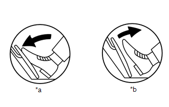
|
*a |
Fully Depressed |
|
*b |
Fully Released |
(a) Connect the Techstream to the DLC3.
(b) Turn the engine switch on (IG).
(c) Turn the Techstream on.
(d) Enter the following menus: Powertrain / Engine / Data List / Accelerator Position Sensor No.1 Voltage and Accelerator Position Sensor No.2 Voltage.
Powertrain > Engine > Data List
|
Tester Display |
|---|
|
Accelerator Position Sensor No.1 Voltage |
|
Accelerator Position Sensor No.2 Voltage |
(e) Fully depress and release the accelerator pedal quickly and repeatedly and confirm that the data monitor value changes in accordance with the operation of the accelerator pedal.
Standard Voltage:
|
Accelerator Pedal Operation |
Accelerator Position Sensor No.1 Voltage |
Accelerator Position Sensor No.2 Voltage |
|---|---|---|
|
Fully Released |
0.5 to 1.1 V |
1.2 to 2.0 V |
|
Fully Depressed |
2.6 to 4.5 V |
3.4 to 4.75 V |
|
Result |
Proceed to |
|---|---|
|
The data monitor value changes in accordance with the operation of the accelerator pedal |
A |
|
The data monitor value does not change in accordance with the operation of the accelerator pedal |
B |
| B |
|
|
|
6. |
CHECK HARNESS AND CONNECTOR (ACCELERATOR PEDAL SENSOR ASSEMBLY - ECM) |
HINT:
Make sure that the connector is properly connected. If it is not, securely connect it and check for DTCs again.
(a) Disconnect the accelerator pedal sensor assembly connector.
(b) Disconnect the ECM connector.
(c) Measure the resistance according to the value(s) in the table below.
Standard Resistance:
|
Tester Connection |
Condition |
Specified Condition |
|---|---|---|
|
A54-6 (VPA) - A47-55 (VPA) |
Always |
Below 1 Ω |
|
A54-5 (EPA) - A47-56 (EPA) |
Always |
Below 1 Ω |
|
A54-4 (VCPA) - A47-57 (VCPA) |
Always |
Below 1 Ω |
|
A54-3 (VPA2) - A47-58 (VPA2) |
Always |
Below 1 Ω |
|
A54-2 (EPA2) - A47-59 (EPA2) |
Always |
Below 1 Ω |
|
A54-1 (VCP2) - A47-60 (VCP2) |
Always |
Below 1 Ω |
|
A54-6 (VPA) or A47-55 (VPA) - Body ground and other terminals |
Always |
10 kΩ or higher |
|
A54-5 (EPA) or A47-56 (EPA) - Body ground and other terminals |
Always |
10 kΩ or higher |
|
A54-4 (VCPA) or A47-57 (VCPA) - Body ground and other terminals |
Always |
10 kΩ or higher |
|
A54-3 (VPA2) or A47-58 (VPA2) - Body ground and other terminals |
Always |
10 kΩ or higher |
|
A54-2 (EPA2) or A47-59 (EPA2) - Body ground and other terminals |
Always |
10 kΩ or higher |
|
A54-1 (VCP2) or A47-60 (VCP2) - Body ground and other terminals |
Always |
10 kΩ or higher |
| OK |
|
| NG |
|
REPAIR OR REPLACE HARNESS OR CONNECTOR |
|
7. |
READ VALUE USING TECHSTREAM (ACCELERATOR POSITION SENSOR NO. 1 VOLTAGE AND ACCELERATOR POSITION SENSOR NO. 2 VOLTAGE) |
(a) Connect the Techstream to the DLC3.
(b) Turn the engine switch on (IG).
(c) Turn the Techstream on.
(d) Enter the following menus: Powertrain / Engine / Data List / Accelerator Position Sensor No.1 Voltage and Accelerator Position Sensor No.2 Voltage.
Powertrain > Engine > Data List
|
Tester Display |
|---|
|
Accelerator Position Sensor No.1 Voltage |
|
Accelerator Position Sensor No.2 Voltage |
(e) While jiggling the ECM connector, confirm that the data monitor value changes.
Standard Voltage:
|
Accelerator Pedal Operation |
Accelerator Position Sensor No.1 Voltage |
Accelerator Position Sensor No.2 Voltage |
|---|---|---|
|
Fully Released |
0.5 to 1.1 V |
1.2 to 2.0 V |
|
Fully Depressed |
2.6 to 4.5 V |
3.4 to 4.75 V |
|
Result |
Proceed to |
|---|---|
|
The data monitor value does not change |
A |
|
The data monitor value changes |
B |
| A |
|
|
|
8. |
CHECK HARNESS AND CONNECTOR (ACCELERATOR PEDAL SENSOR ASSEMBLY - ECM) |
HINT:
Make sure that the connector is properly connected. If it is not, securely connect it and check for DTCs again.
(a) Disconnect the accelerator pedal sensor assembly connector.
(b) Disconnect the ECM connector.
(c) Measure the resistance according to the value(s) in the table below.
Standard Resistance:
|
Tester Connection |
Condition |
Specified Condition |
|---|---|---|
|
A54-6 (VPA) - A47-55 (VPA) |
Always |
Below 1 Ω |
|
A54-5 (EPA) - A47-56 (EPA) |
Always |
Below 1 Ω |
|
A54-4 (VCPA) - A47-57 (VCPA) |
Always |
Below 1 Ω |
|
A54-3 (VPA2) - A47-58 (VPA2) |
Always |
Below 1 Ω |
|
A54-2 (EPA2) - A47-59 (EPA2) |
Always |
Below 1 Ω |
|
A54-1 (VCP2) - A47-60 (VCP2) |
Always |
Below 1 Ω |
|
A54-6 (VPA) or A47-55 (VPA) - Body ground and other terminals |
Always |
10 kΩ or higher |
|
A54-5 (EPA) or A47-56 (EPA) - Body ground and other terminals |
Always |
10 kΩ or higher |
|
A54-4 (VCPA) or A47-57 (VCPA) - Body ground and other terminals |
Always |
10 kΩ or higher |
|
A54-3 (VPA2) or A47-58 (VPA2) - Body ground and other terminals |
Always |
10 kΩ or higher |
|
A54-2 (EPA2) or A47-59 (EPA2) - Body ground and other terminals |
Always |
10 kΩ or higher |
|
A54-1 (VCP2) or A47-60 (VCP2) - Body ground and other terminals |
Always |
10 kΩ or higher |
| OK |
|
REPLACE ECM
|
| NG |
|
REPAIR OR REPLACE HARNESS OR CONNECTOR |
|
|
|