| 
                     
                        | Last Modified: 01-27-2025 | 6.11:8.1.0 | Doc ID: RM100000001D0FQ |  
                        | Model Year Start: 2019 | Model: GR Corolla | Prod Date Range: [06/2018 -                    
                                       ] |  
                        | Title: STEERING COLUMN: STEERING SYSTEM: ADJUSTMENT; 2019 - 2025 MY Corolla Corolla Hatchback Corolla HV GR Corolla [06/2018 -        ] |  ADJUSTMENTPROCEDURE1.   STEERING WHEEL OFF CENTER ADJUSTMENT PROCEDURE (a) Inspect steering wheel off center. (1) Turn the steering wheel assembly to the center position. 
                     
                        
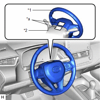
                           | (2) Apply masking tape to the top center of the steering wheel assembly and upper steering column cover. | 
                                 
                                    |   |  
                                    | 


                                                | *1 | Steering Wheel Assembly |  
                                                | *2 | Upper Steering Column Cover |  
                                                | *a | Masking Tape |  |  |  (3) Drive the vehicle in a straight line for 100 m (328 ft.) at a constant speed of 56 km/h (35 mph), while holding the steering wheel assembly to maintain the course. 
                     
                        
                           | (4) Draw a line on the masking tape as shown in the illustration. | 
                                 
                                    |   |  
                                    | 


                                                | *1 | Upper Steering Column Cover |  
                                                | *2 | Steering Wheel Assembly |  
                                                | *a | Marked Line |  |  |  
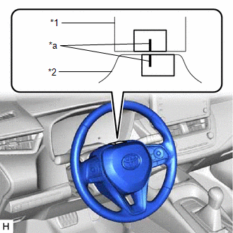
(5) Turn the steering wheel assembly to the center position. 
                     
                        
                           | (6) Draw a new line on the masking tape on the steering wheel assembly as shown in the illustration. | 
                                 
                                    |   |  
                                    | 


                                                | *1 | Upper Steering Column Cover |  
                                                | *2 | Steering Wheel Assembly |  
                                                | *a | Marked Line |  |  |  
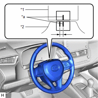
(7) Measure the distance between the 2 lines on the masking tape on the steering wheel assembly. (8) Convert the measured distance to the steering angle. 
                     HINT: 
                        
Measured distance of 1 mm (0.0394 in.) = Steering angle of approximately 1 degree
Make a note of the steering angle.
 (b) Adjust the steering angle. 
                     
                        
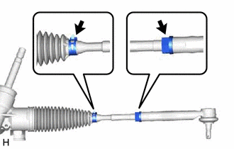
                           | (1) Put matchmarks on the tie rod assemblies LH and RH and steering rack end sub-assembly respectively. |  |  
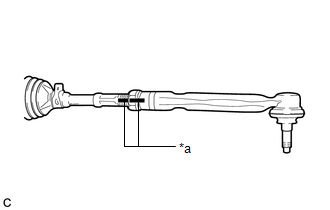
(2) Using a paper gauge, measure the thread length of the steering rack end sub-assemblies. 
                     HINT: 
                        
Measure both RH and LH sides.
Make a note of the measured values.


                           | (3) Remove the steering rack boot clips from the RH and LH steering rack boots. |  |  (4) Loosen the RH and LH lock nuts. (5) Turn the RH and LH steering rack end sub-assemblies by the same amount (but in different directions) according to the measured steering angle. HINT: One 360 degree turn of a steering rack end (1.5 mm (0.0591 in.) horizontal movement) equals 9.2 degrees of steering angle. (6) Tighten the RH and LH lock nuts to the specified torque. Torque:  74 N·m {755 kgf·cm, 55 ft·lbf} NOTICE: Make sure that the difference in thread length between the RH and LH steering rack end sub-assemblies is within 1.5 mm (0.0591 in.). (7) Install the RH and LH steering rack boot clips. |