| Last Modified: 01-27-2025 | 6.11:8.1.0 | Doc ID: RM100000001CZJ0 |
| Model Year Start: 2019 | Model: Corolla Hatchback | Prod Date Range: [06/2018 - 03/2019] |
| Title: EG60 (MANUAL TRANSMISSION / TRANSAXLE): MANUAL TRANSAXLE UNIT: DISASSEMBLY; 2019 - 2020 MY Corolla Corolla Hatchback [06/2018 - 03/2019] | ||
DISASSEMBLY
PROCEDURE
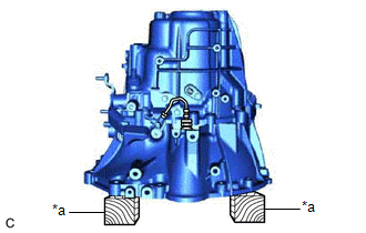
1. SECURE MANUAL TRANSAXLE ASSEMBLY
|
(a) Place the manual transaxle assembly on wooden blocks. |
|
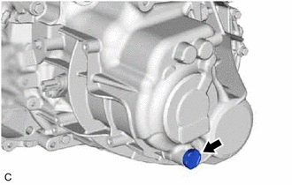
2. REMOVE MANUAL TRANSMISSION FILLER PLUG
|
(a) Remove the manual transmission filler plug and gasket from the manual transmission case. |
|
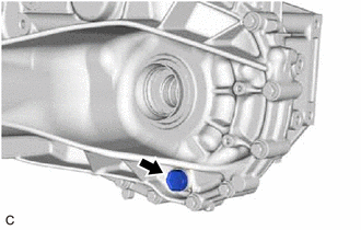
3. REMOVE MANUAL TRANSMISSION DRAIN PLUG
|
(a) Remove the manual transmission drain plug and gasket from the manual transmission case. |
|
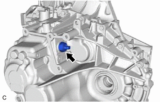
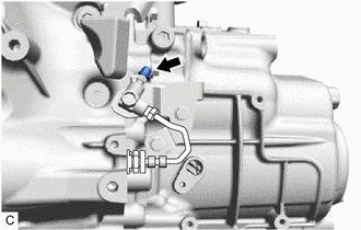
4. REMOVE BACK-UP LIGHT SWITCH ASSEMBLY
|
(a) Using a 27 mm deep socket wrench, remove the back-up light switch assembly and gasket from the manual transmission case. |
|
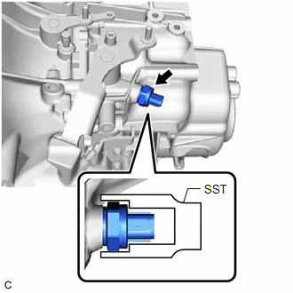
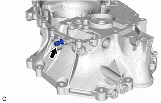
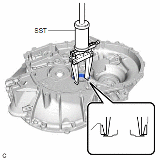
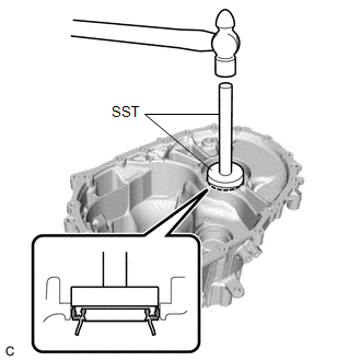
5. REMOVE NEUTRAL POSITION SWITCH
|
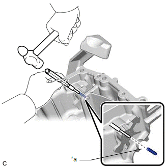
(a) Using SST, remove the neutral position switch and gasket from the manual transmission case. SST: 09816-30010 |
|
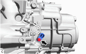
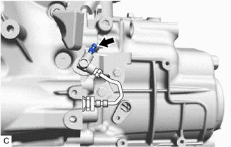
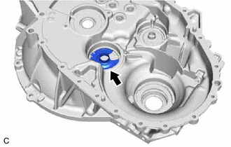
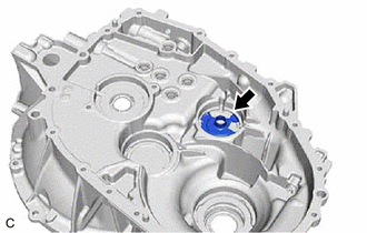
6. REMOVE TRANSMISSION REVOLUTION SENSOR
|
(a) Remove the bolt and transmission revolution sensor from the manual transmission case. |
|
|
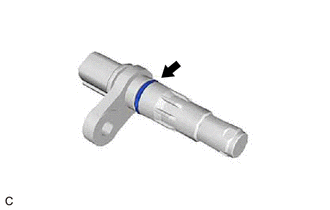
(b) Remove the O-ring from the transmission revolution sensor. |
|
7. REMOVE RELEASE CYLINDER BLEEDER PLUG CAP
|
(a) Remove the release cylinder bleeder plug cap from the release cylinder bleeder plug. |
|
8. REMOVE RELEASE CYLINDER BLEEDER PLUG
|
(a) Remove the release cylinder bleeder plug from the clutch release bleeder sub-assembly. |
|
9. REMOVE CLUTCH RELEASE CYLINDER WITH BEARING ASSEMBLY
Click here
![2019 MY Corolla Corolla Hatchback [06/2018 - 01/2019]; CLUTCH: CLUTCH UNIT (for EG60): REMOVAL+](/t3Portal/stylegraphics/info.gif)
10. REMOVE CLUTCH RELEASE CYLINDER WITH BEARING ASSEMBLY TO BLEEDER TUBE
Click here
11. REMOVE CLUTCH RELEASE BLEEDER SUB-ASSEMBLY
Click here
12. REMOVE LOCK BALL PIN
|
(a) Using a 10 mm hexagon socket wrench, remove the shift and select lever shaft straight screw with head plug from the manual transmission case. |
|
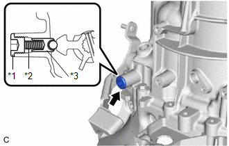
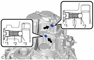
(b) Using a Magnet Hand, remove the No. 2 lock ball pin return spring and lock ball pin from the manual transmission case.
13. REMOVE NO. 2 LOCK BALL PIN
|
(a) Using a 10 mm hexagon socket wrench, remove the shift and select lever shaft straight screw with head plug from the transaxle(MTM) case sub-assembly. |
|
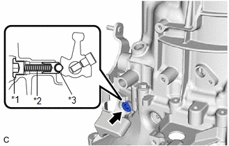
(b) Using a Magnet Hand, remove the No. 1 lock ball pin return spring and No. 2 lock ball pin from the transaxle(MTM) case sub-assembly.
14. REMOVE SHIFT DETENT BALL
|
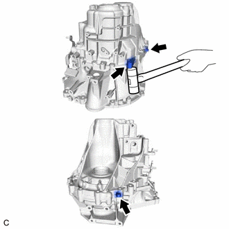
(a) Using a 6 mm hexagon socket wrench, remove the shift detent ball plug from the transaxle(MTM) case sub-assembly. |
|
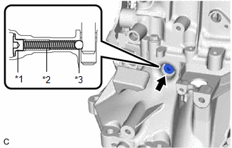
(b) Using a Magnet Hand, remove the No. 2 shift detent ball compression spring and shift detent ball from the transaxle(MTM) case sub-assembly.
|
(c) Using a 6 mm hexagon socket wrench, remove the 2 shift detent ball plugs from the manual transmission case. |
|
(d) Using a Magnet Hand, remove the 2 shift detent ball compression springs and 2 shift detent balls from the manual transmission case.
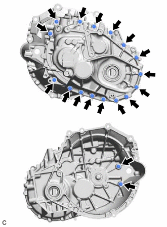
15. REMOVE MANUAL TRANSMISSION CASE
|
(a) Remove the 18 bolts. |
|
|
(b) Using a plastic hammer, separate the manual transmission case from the transaxle(MTM) case sub-assembly. NOTICE: Do not damage the manual transmission case. |
|
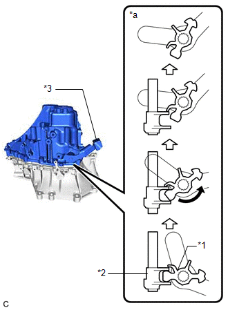
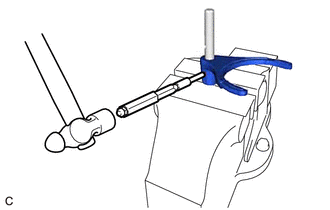
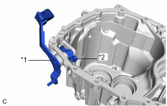
(c) While turning the outer No. 1 shift lever counterclockwise, remove the manual transmission case from the transaxle (MTM) case sub-assembly as shown in the illustration.
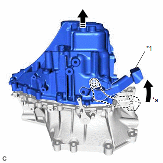
|
*1 |
Outer No. 1 Shift Lever |
|
*a |
Turn Counterclockwise |
NOTICE:
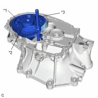
As the outer No. 1 shift lever will turn clockwise strongly under its own weight when the manual transmission case is lifted a certain amount and the inner No. 1 shift lever and inner No. 2 shift lever become disengaged, make sure to hold the outer No. 1 shift lever firmly.
|
*1 |
Inner No. 1 Shift Lever |
|
*2 |
Inner No. 2 Shift Lever |
|
*3 |
Outer No. 1 Shift Lever |
|
*a |
Movement Inside Manual Transaxle Assembly |
16. REMOVE INNER SELECT LEVER SET BOLT
|
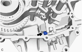
(a) Using a 6 mm hexagon socket wrench, remove the inner select lever set bolt. |
|
17. REMOVE OUTER SELECT LEVER
|
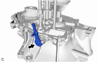
(a) Remove the outer select lever from the transaxle(MTM) case sub-assembly. |
|
18. REMOVE SHIFT AND SELECT LEVER SHAFT ASSEMBLY
|
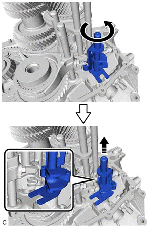
(a) Rotate the shift and select lever shaft assembly counterclockwise to the position shown in the illustration and remove it from the transaxle (MTM) case sub-assembly. |
|
19. REMOVE INNER SELECT LEVER
|
(a) Remove the inner select lever from the transaxle(MTM) case sub-assembly. |
|
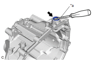
20. REMOVE OUTER SELECT LEVER OIL SEAL
|
(a) Using a screwdriver with its tip wrapped with protective tape, remove the outer select lever oil seal from the transaxle(MTM) case sub-assembly. NOTICE: Do not damage the transaxle(MTM) case sub-assembly. |
|
21. REMOVE INPUT SHAFT ASSEMBLY
|
(a) Remove the input shaft assembly together with the output shaft assembly, No. 1 fork shaft assembly, No. 2 gear shift fork assembly and No. 3 gear shift fork assembly from the transaxle(MTM) case sub-assembly. NOTICE: To prevent damage to the front output shaft bearing (inner race), slightly raise the differential case assembly. |
|
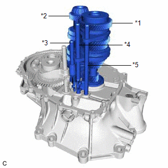
(b) Remove the No. 1 fork shaft assembly, No. 2 gear shift fork assembly and No. 3 gear shift fork assembly from the input shaft assembly and output shaft assembly.
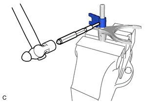
22. REMOVE NO. 1 GEAR SHIFT HEAD
|
(a) Using a 5 mm pin punch and hammer, remove the shift head set slotted spring pin and No. 1 gear shift head from the No. 1 gear shift fork shaft. |
|
23. REMOVE NO. 1 GEAR SHIFT FORK ASSEMBLY
|
(a) Using a 5 mm pin punch and hammer, remove the shift fork slotted pin and No. 1 gear shift fork assembly from the No. 1 gear shift fork shaft. |
|
24. REMOVE DIFFERENTIAL CASE ASSEMBLY
|
(a) Remove the differential case assembly together with the No. 2 output shaft assembly and No. 4 fork shaft assembly from the transaxle(MTM) case sub-assembly. |
|
(b) Remove the No. 4 fork shaft assembly from the No. 2 output shaft assembly.
25. REMOVE NO. 4 GEAR SHIFT FORK
|
(a) Remove the bolt and No. 4 gear shift fork from the No. 4 gear shift fork shaft. |
|
26. REMOVE FRONT DIFFERENTIAL CASE FRONT TAPERED ROLLER BEARING
|
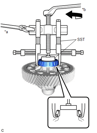
(a) Using SST, remove the front differential case front tapered roller bearing (outer race) from the transaxle(MTM) case sub-assembly. SST: 09308-36010 NOTICE:
|
|
|
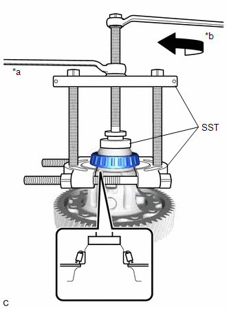
(b) Using SST, remove the front differential case front tapered roller bearing (inner race) from the differential case assembly. SST: 09950-00020 SST: 09950-00030 SST: 09950-60011 09951-00500 |
|
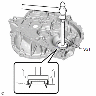
27. REMOVE FRONT DIFFERENTIAL CASE REAR TAPERED ROLLER BEARING
|
(a) Using SST, remove the front differential case rear tapered roller bearing (outer race) and front differential case rear shim from the manual transmission case. SST: 09308-36010 NOTICE: Do not damage the manual transmission case. |
|
|
(b) Using SST, remove the front differential case rear tapered roller bearing (inner race) from the differential case assembly. SST: 09950-40011 09951-04010 09952-04010 09953-04020 09954-04010 09955-04061 09957-04010 09958-04011 SST: 09950-60011 09951-00500 |
|
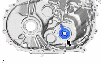
28. REMOVE TRANSMISSION MAGNET
|
(a) Remove the transmission magnet from the transaxle(MTM) case sub-assembly. |
|
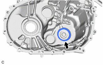
29. REMOVE BREATHER PLUG
|
(a) Remove the breather plug from the transaxle(MTM) case sub-assembly. |
|
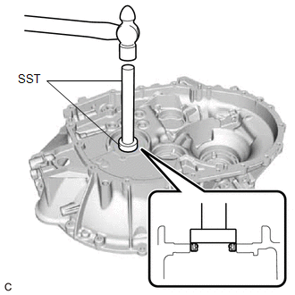
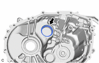
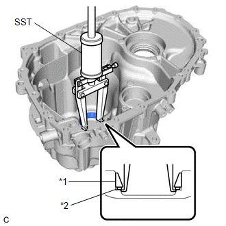
30. REMOVE FRONT OUTPUT SHAFT BEARING (OUTER RACE)
|
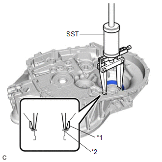
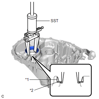
(a) Using SST, remove the front output shaft bearing (outer race) from the transaxle(MTM) case sub-assembly. SST: 09308-00010 NOTICE: Do not damage the transaxle(MTM) case sub-assembly. |
|
31. REMOVE OUTPUT SHAFT(MTM) COVER
|
(a) Remove the output shaft(MTM) cover from the transaxle(MTM) case sub-assembly. |
|
32. REMOVE REVERSE GEAR SHAFT COVER
|
(a) Remove the reverse gear shaft cover from the transaxle(MTM) case sub-assembly. |
|
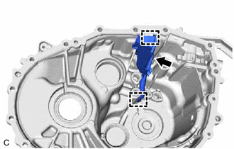
33. REMOVE FRONT DIFFERENTIAL OIL BAFFLE
|
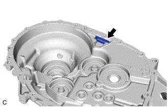
(a) Remove the front differential oil baffle from the transaxle(MTM) case sub-assembly. |
|
34. REMOVE FRONT TRANSAXLE CASE OIL SEAL
|
(a) Using SST and a hammer, remove the front transaxle case oil seal from the transaxle(MTM) case sub-assembly. SST: 09950-60011 09951-00360 SST: 09950-70010 09951-07150 |
|
35. REMOVE FRONT DRIVE SHAFT OIL SEAL RH
|
(a) Using SST and a hammer, remove the front drive shaft oil seal RH from the transaxle(MTM) case sub-assembly. SST: 09950-60011 09951-00590 SST: 09950-70010 09951-07200 |
|
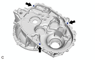
36. REMOVE TRANSAXLE CASE STRAIGHT PIN
|
(a) Remove the 3 transaxle case straight pins from the transaxle(MTM) case sub-assembly. |
|
37. REMOVE REAR REVERSE GEAR SHAFT BEARING SHIM
|
(a) Remove the rear reverse gear shaft bearing shim from the manual transmission case. |
|
38. REMOVE REAR INPUT SHAFT BEARING SHIM
|
(a) Remove the rear input shaft bearing shim from the manual transmission case. |
|
39. REMOVE INPUT SHAFT(MTM) COVER
|
(a) Remove the input shaft(MTM) cover from the manual transmission case. |
|
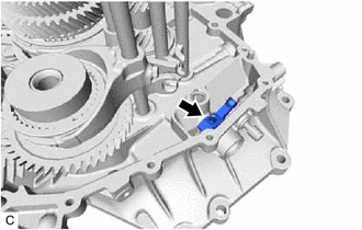
40. REMOVE NO. 1 OIL RECEIVER PIPE(MTM)
|
(a) Disengage the 2 guides and remove the No. 1 oil receiver pipe(MTM) from the manual transmission case. |
|
41. REMOVE OUTER NO. 1 SHIFT LEVER
|
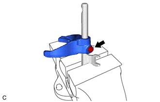
(a) Using a 5 mm pin punch and hammer, remove the inner shift lever slotted spring pin from the inner No. 1 shift lever. NOTICE: Perform this step carefully so that the inner shift lever slotted spring pin does not fly out. HINT: When removing the inner shift lever slotted spring pin, align the inner shift lever slotted spring pin with the hole in the neutral position switch. |
|
|
(b) Remove the outer No. 1 shift lever and inner No. 1 shift lever from the manual transmission case. |
|
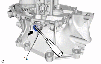
42. REMOVE OUTER SHIFT LEVER OIL SEAL
|
(a) Using a screwdriver with its tip wrapped with protective tape, remove the outer shift lever oil seal from the manual transmission case. NOTICE: Do not damage the manual transmission case. |
|
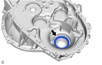
43. REMOVE REAR OUTPUT SHAFT BEARING (OUTER RACE)
|
(a) Using SST, remove the rear output shaft bearing (outer race) and rear output shaft bearing shim from the manual transmission case. SST: 09308-00010 NOTICE: Do not damage the manual transmission case. |
|
44. REMOVE FRONT DRIVE SHAFT OIL SEAL LH
|
(a) Using SST and a hammer, remove the front drive shaft oil seal LH from the manual transmission case. SST: 09950-60011 09951-00620 SST: 09950-70010 09951-07150 |
|
|
|
|