| Last Modified: 07-31-2024 | 6.11:8.1.0 | Doc ID: RM100000001CYGV |
| Model Year Start: 2019 | Model: GR Corolla | Prod Date Range: [06/2018 - 01/2019] |
| Title: THEFT DETERRENT / KEYLESS ENTRY: ELECTRICAL KEY OSCILLATOR (for Front Floor): REMOVAL; 2019 MY Corolla Corolla Hatchback Corolla HV GR Corolla [06/2018 - 01/2019] | ||
REMOVAL
CAUTION / NOTICE / HINT
The necessary procedures (adjustment, calibration, initialization or registration) that must be performed after parts are removed and installed, or replaced during No. 1 indoor electrical key antenna assembly removal/installation are shown below.
Necessary Procedure After Parts Removed/Installed/Replaced
|
Replaced Part or Performed Procedure |
Necessary Procedure |
Effect/Inoperative Function When Necessary Procedures are not Performed |
Link |
|---|---|---|---|
|
Disconnect cable from negative battery terminal |
Perform steering sensor zero point calibration |
Lane Control System |
|
|
Pre-collision System |
|||
|
Lighting System (w/ AFS)(EXT) |
|||
|
Initialize back door lock |
Power Door Lock Control System |
NOTICE:
- After the engine switch is turned off, the radio and display receiver assembly records various types of memory and settings. As a result, after turning the engine switch off, make sure to wait at least 85 seconds before disconnecting the cable from the negative (-) battery terminal. (for Audio and Visual System)
- After the engine switch is turned off, the radio and display receiver assembly records various types of memory and settings. As a result, after turning the engine switch off, make sure to wait at least 85 seconds before disconnecting the cable from the negative (-) battery terminal. (for Navigation System)
PROCEDURE
1. PRECAUTION
NOTICE:
After turning the engine switch off, waiting time may be required before disconnecting the cable from the negative (-) battery terminal. Therefore, make sure to read the disconnecting the cable from the negative (-) battery terminal notices before proceeding with work.
2. DISCONNECT CABLE FROM NEGATIVE BATTERY TERMINAL
3. REMOVE NO. 1 INSTRUMENT PANEL UNDER COVER SUB-ASSEMBLY
4. REMOVE LOWER CENTER INSTRUMENT PANEL FINISH PANEL
5. REMOVE FRONT CONSOLE UPPER PANEL GARNISH
6. REMOVE SHIFT LEVER KNOB SUB-ASSEMBLY (for Manual Transaxle)
7. REMOVE SHIFT LEVER KNOB SUB-ASSEMBLY (for CVT)
8. REMOVE UPPER FRONT CONSOLE PANEL SUB-ASSEMBLY (for Manual Transaxle)
9. REMOVE POSITION INDICATOR HOUSING ASSEMBLY (for CVT)
10. REMOVE CONSOLE CUP HOLDER BOX SUB-ASSEMBLY
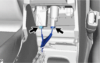
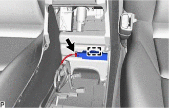
11. REMOVE NO. 1 INDOOR ELECTRICAL KEY ANTENNA ASSEMBLY
|
(a) Disconnect the 2 connectors. |
|
|
(b) Disconnect the connector. |
|
(c) Disengage the clamp to remove the No. 1 indoor electrical key antenna assembly.
NOTICE:
Be careful when removing the No. 1 indoor electrical key antenna assembly. If the No. 1 indoor electrical key antenna assembly is dropped, replace it with a new one.
|
|
|
![2019 - 2022 MY Corolla Corolla Hatchback GR Corolla [06/2018 - 09/2022]; PRE-COLLISION: PRE-COLLISION SYSTEM (for Gasoline Model): INITIALIZATION](/t3Portal/stylegraphics/info.gif)

