| Last Modified: 05-13-2024 | 6.11:8.1.0 | Doc ID: RM100000001CVFS |
| Model Year Start: 2019 | Model: GR Corolla | Prod Date Range: [06/2018 - 01/2019] |
| Title: AUDIO / VIDEO: AUDIO AND VISUAL SYSTEM (for Gasoline Model with Dual Knob Type): Mute Signal Circuit between Radio Receiver and Telematics Transceiver; 2019 MY Corolla Corolla Hatchback GR Corolla [06/2018 - 01/2019] | ||
|
Mute Signal Circuit between Radio Receiver and Telematics Transceiver |
DESCRIPTION
The DCM (telematics transceiver) sends a mute signal to the radio and display receiver assembly.
The radio and display receiver assembly controls the volume according to the mute signal from the DCM (telematics transceiver).
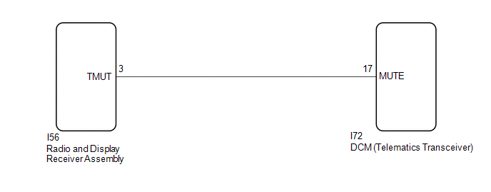
WIRING DIAGRAM
CAUTION / NOTICE / HINT
NOTICE:
-
Depending on the parts that are replaced during vehicle inspection or maintenance, performing initialization, registration or calibration may be needed. Refer to Precaution for Audio and Visual System.
Click here
![2019 MY Corolla Corolla Hatchback GR Corolla [06/2018 - 01/2019]; AUDIO / VIDEO: AUDIO AND VISUAL SYSTEM (for Gasoline Model with Dual Knob Type): PRECAUTION](/t3Portal/stylegraphics/info.gif)
-
When replacing the radio and display receiver assembly, always replace it with a new one. If a radio and display receiver assembly which was installed to another vehicle is used, the following may occur:
- A communication malfunction DTC may be stored.
- The radio and display receiver assembly may not operate normally.
-
Before replacing the DCM (telematics transceiver), refer to Registration.
Click here
PROCEDURE
|
1. |
INSPECT DCM (TELEMATICS TRANSCEIVER) |
|
(a) Measure the voltage according to the value(s) in the table below. Standard Voltage:
|
|
| OK |

|
PROCEED TO NEXT SUSPECTED AREA SHOWN IN PROBLEM SYMPTOMS TABLE |
|

|
2. |
CHECK HARNESS AND CONNECTOR (RADIO AND DISPLAY RECEIVER ASSEMBLY - DCM (TELEMATICS TRANSCEIVER)) |
(a) Disconnect the I56 radio and display receiver assembly connector.
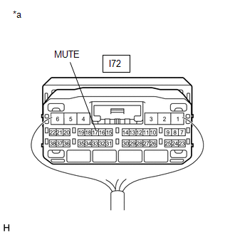
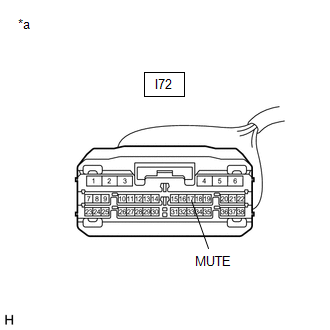
(b) Disconnect the I72 DCM (telematics transceiver) connector.
(c) Measure the resistance according to the value(s) in the table below.
Standard Resistance:
|
Tester Connection |
Condition |
Specified Condition |
|---|---|---|
|
I56-3 (TMUT) - I72-17 (MUTE) |
Always |
Below 1 Ω |
|
I56-3 (TMUT) or I72-17 (MUTE) - Body ground |
Always |
10 kΩ or higher |
| NG |
|
REPAIR OR REPLACE HARNESS OR CONNECTOR |
|
|
3. |
INSPECT RADIO AND DISPLAY RECEIVER ASSEMBLY |
(a) Disconnect the I72 DCM (telematics transceiver) connector.
|
(b) Measure the voltage according to the value(s) in the table below. Standard Voltage:
|
|
| OK |
|
Click here Click here REPLACE DCM (TELEMATICS TRANSCEIVER) |
| NG |
|
|
|
|