| Last Modified: 05-13-2024 | 6.11:8.1.0 | Doc ID: RM100000001CJJK |
| Model Year Start: 2019 | Model: Corolla Hatchback | Prod Date Range: [06/2018 - ] |
| Title: M20A-FKS (ENGINE MECHANICAL): ENGINE UNIT: INSPECTION; 2019 - 2025 MY Corolla Corolla Hatchback [06/2018 - ] | ||
INSPECTION
PROCEDURE
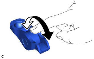
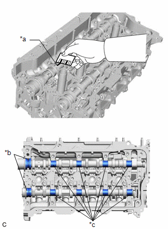
1. INSPECT NO. 1 VALVE ROCKER ARM SUB-ASSEMBLY
|
(a) Turn the roller by hand to check that it turns smoothly. HINT: If the roller does not turn smoothly, replace the No. 1 valve rocker arm sub-assembly. |
|
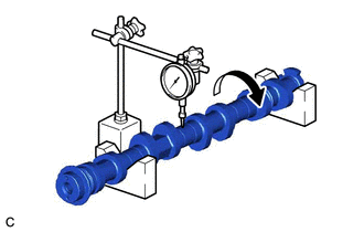
2. INSPECT INTAKE CAMSHAFT SUB-ASSEMBLY
|
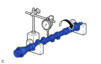
(a) Inspect the intake camshaft sub-assembly for runout. (1) Place the intake camshaft sub-assembly on V-blocks. (2) Using a dial indicator, measure the runout at the center journal. Maximum Runout: 0.03 mm (0.00118 in.) HINT:
|
|
|
(b) Inspect the cam lobes. (1) Using a micrometer, measure the cam lobe height. Standard Cam Lobe Height: 42.615 to 42.715 mm (1.67775 to 1.68169 in.) Minimum Cam Lobe Height: 42.505 mm (1.67342 in.) HINT: If the cam lobe height is less than the minimum, replace the intake camshaft sub-assembly. |
|
|
(c) Inspect the intake camshaft sub-assembly journals. (1) Using a micrometer, measure the journal diameter. Standard Journal Diameter:
HINT: If the journal diameter is not as specified, check the intake camshaft sub-assembly oil clearance. Click here
|
|
3. INSPECT EXHAUST CAMSHAFT SUB-ASSEMBLY
|
(a) Inspect the exhaust camshaft sub-assembly for runout. (1) Place the exhaust camshaft sub-assembly on V-blocks. (2) Using a dial indicator, measure the runout at the center journal. Maximum Runout: 0.03 mm (0.00118 in.) HINT:
|
|
|
(b) Inspect the cam lobes. (1) Using a micrometer, measure the cam lobe height. Standard Cam Lobe Height:
Minimum Cam Lobe Height:
HINT: If the cam lobe height is less than the minimum, replace the exhaust camshaft sub-assembly. |
|
|
(c) Inspect the exhaust camshaft sub-assembly journals. (1) Using a micrometer, measure the journal diameter. Standard Journal Diameter:
HINT: If the journal diameter is not as specified, check the camshaft oil clearance. Click here
|
|
4. INSPECT CAMSHAFT OIL CLEARANCE
(a) Clean the No. 1 camshaft bearing cap, No. 2 camshaft bearing cap, 2 No. 3 camshaft bearing caps, camshaft housing sub-assembly and camshaft journals.
(b) Place the intake camshaft sub-assembly and exhaust camshaft sub-assembly on the camshaft housing sub-assembly.
|
(c) Lay a strip of Plastigage across each of the camshaft journals. |
|
(d) Install the camshaft bearing caps.
Click here
![2019 - 2023 MY Corolla Corolla Hatchback [06/2018 - 03/2023]; M20A-FKS (ENGINE MECHANICAL): ENGINE UNIT: REASSEMBLY+](/t3Portal/stylegraphics/info.gif)
NOTICE:
Do not turn the camshafts.
(e) Remove the camshaft bearing caps.
Click here
|
(f) Measure the Plastigage at its widest point. Standard Oil Clearance (for intake camshaft sub-assembly):
Standard Oil Clearance (for exhaust camshaft sub-assembly):
Maximum Oil Clearance (for intake camshaft sub-assembly):
Maximum Oil Clearance (for exhaust camshaft sub-assembly):
NOTICE: Completely remove the Plastigage after the inspection. HINT: If the oil clearance is more than the maximum, replace the intake camshaft sub-assembly or exhaust camshaft sub-assembly. If necessary, replace the camshaft housing sub-assembly. |
|
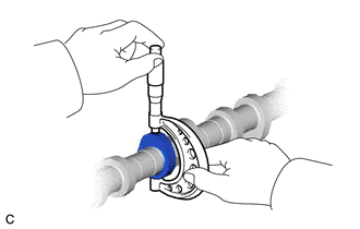
5. INSPECT CHAIN SUB-ASSEMBLY
|
(a) Using a spring scale, pull the chain sub-assembly with a force of 147 N (15 kgf, 33.0 lbf) as shown in the illustration. |
|
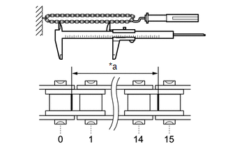
(b) Using a vernier caliper, measure the length of 15 links.
Maximum Chain Elongation:
116.30 mm (4.58 in.)
NOTICE:
Perform the measurement at 3 random places. Use the average of the measurements.
HINT:
If the average elongation is more than the maximum, replace the chain sub-assembly.
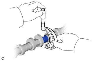
6. INSPECT OIL PUMP DRIVE CHAIN SUB-ASSEMBLY
|
(a) Using a spring scale, pull the oil pump drive chain sub-assembly with a force of 147 N (15 kgf, 33.0 lbf) as shown in the illustration. |
|

(b) Using a vernier caliper, measure the length of 15 links.
Maximum Chain Elongation:
116.30 mm (4.58 in.)
NOTICE:
Perform the measurement at 3 random places. Use the average of the measurements.
HINT:
If the average elongation is more than the maximum, replace the oil pump drive chain sub-assembly.
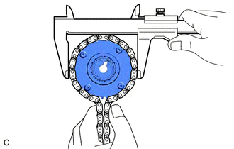
7. INSPECT OIL PUMP DRIVE SPROCKET
|
(a) Place the oil pump drive chain sub-assembly around the oil pump drive sprocket. |
|
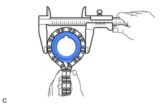
(b) Using a vernier caliper, measure the diameter of the oil pump drive sprocket and oil pump drive chain sub-assembly.
Minimum Gear Diameter (with Oil Pump Drive Chain Sub-assembly):
51.35 mm (2.02 in.)
NOTICE:
The vernier caliper must be in contact with the chain rollers when measuring.
HINT:
If the diameter is less than the minimum, replace the oil pump drive chain sub-assembly and oil pump drive sprocket.
8. INSPECT OIL PUMP DRIVE SHAFT SPROCKET
|
(a) Place the oil pump drive chain sub-assembly around the oil pump drive shaft sprocket. |
|
(b) Using a vernier caliper, measure the diameter of the oil pump drive shaft sprocket and oil pump drive chain sub-assembly.
Minimum Gear Diameter (with Oil Pump Drive Chain Sub-assembly):
51.35 mm (2.02 in.)
NOTICE:
The vernier caliper must be in contact with the chain rollers when measuring.
HINT:
If the diameter is less than the minimum, replace the oil pump drive chain sub-assembly and oil pump drive shaft sprocket.
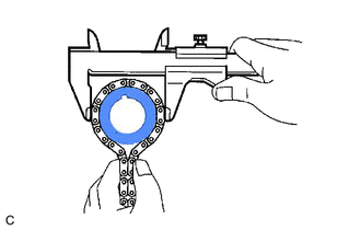
9. INSPECT CAMSHAFT TIMING GEAR ASSEMBLY
|
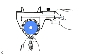
(a) Place the chain sub-assembly around the camshaft timing gear assembly. |
|
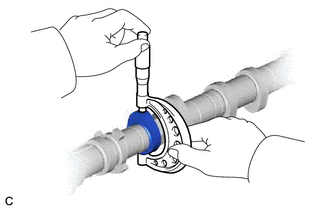
(b) Using a vernier caliper, measure the diameter of the camshaft timing gear assembly and chain sub-assembly.
Minimum Gear Diameter (with Chain Sub-assembly):
100.01 mm (3.94 in.)
NOTICE:
The vernier caliper must be in contact with the chain rollers when measuring.
HINT:
If the diameter is less than the minimum, replace the chain sub-assembly and camshaft timing gear assembly.
10. INSPECT CAMSHAFT TIMING EXHAUST GEAR ASSEMBLY
|
(a) Place the chain sub-assembly around the camshaft timing exhaust gear assembly. |
|

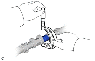
(b) Using a vernier caliper, measure the diameter of the camshaft timing exhaust gear assembly and chain sub-assembly.
Minimum Gear Diameter (with Chain Sub-assembly):
100.01 mm (3.94 in.)
NOTICE:
The vernier caliper must be in contact with the chain rollers when measuring.
HINT:
If the diameter is less than the minimum, replace the chain sub-assembly and camshaft timing exhaust gear assembly.
11. INSPECT CRANKSHAFT TIMING SPROCKET
|
(a) Place the chain sub-assembly around the crankshaft timing sprocket. |
|
(b) Using a vernier caliper, measure the diameter of the crankshaft timing sprocket and chain sub-assembly.
Minimum Sprocket Diameter (with Chain Sub-assembly):
51.35 mm (2.02 in.)
NOTICE:
The vernier caliper must be in contact with the chain rollers when measuring.
HINT:
If the diameter is less than the minimum, replace the chain sub-assembly and crankshaft timing sprocket.
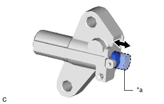
12. INSPECT NO. 1 CHAIN TENSIONER ASSEMBLY
|
(a) Push the plunger and check that it moves smoothly. HINT: If the plunger does not move smoothly, replace the No. 1 chain tensioner assembly. |
|
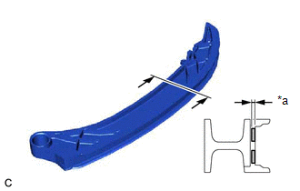
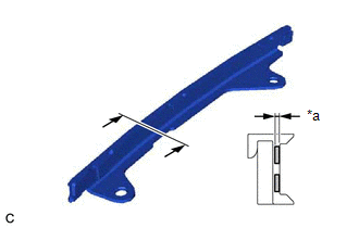
13. INSPECT CHAIN TENSIONER SLIPPER
|
(a) Using a vernier caliper, measure the wear depth of the chain tensioner slipper. Maximum Depth: 1.0 mm (0.0394 in.) HINT: If the depth is more than the maximum, replace the chain tensioner slipper. |
|
14. INSPECT NO. 1 CHAIN VIBRATION DAMPER
|
(a) Using a vernier caliper, measure the wear depth of the No. 1 chain vibration damper. Maximum Depth: 1.0 mm (0.0394 in.) HINT: If the depth is more than the maximum, replace the No. 1 chain vibration damper. |
|
15. INSPECT CYLINDER HEAD SET BOLT
(a) for 140 mm cylinder head set bolt:
|
(1) Using a vernier caliper, measure the diameter of the threads at the measurement point. Standard Diameter: 10.7 to 10.9 mm (0.421 to 0.429 in.) Minimum Diameter: 10.6 mm (0.417 in.) Measurement Point (Distance from the Seat): 105 mm (4.13 in.) HINT:
|
|
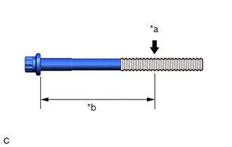
(b) for 130 mm cylinder head set bolt:
|
(1) Using a vernier caliper, measure the diameter of the threads at the measurement point. Standard Diameter: 9.7 to 9.9 mm (0.382 to 0.390 in.) Minimum Diameter: 9.6 mm (0.378 in.) Measurement Point (Distance from the Seat): 115 mm (4.53 in.) HINT:
|
|
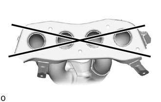
16. INSPECT EXHAUST MANIFOLD (TWC: Front Catalyst)
|
(a) Using a precision straightedge and feeler gauge, check the surface that contacts the cylinder head sub-assembly for warpage. Maximum Warpage: 0.7 mm (0.0276 in.) HINT: If the warpage is more than the maximum, replace the exhaust manifold (TWC: Front Catalyst). |
|
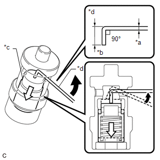
17. INSPECT OIL NOZZLE VALVE SUB-ASSEMBLY
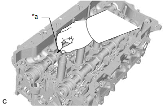
(a) Using a piece of wire, check that the check valve is not stuck.
|
*a |
1 mm (0.0394 in.) |
|
*b |
5 mm (0.197 in.) |
|
*c |
Check Valve |
|
*d |
Wire |

|
Move the wire in this direction. |

|
Movement of Check Valve |
HINT:
- Form a 1 mm (0.0394 in.) diameter piece of wire to the shape shown in the illustration.
- If the check valve is stuck, replace the oil nozzle valve sub-assembly with a new one.
|
(b) Connect a hose to the oil nozzle valve sub-assembly |
|
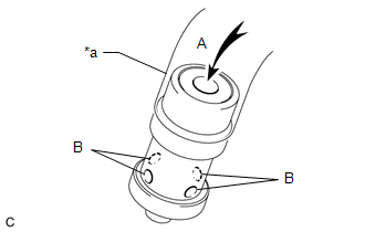
(c) Check that air does not leak from the port (B) when blowing air into the port (A).
HINT:
If air leaks from the port (B), replace the oil nozzle valve sub-assembly with a new one.
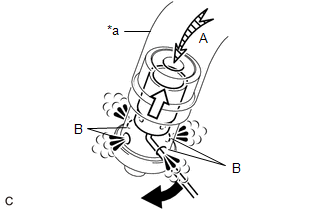
(d) With the check valve depressed using a piece of wire, check that air flows from the port (B) when blowing air into the port (A).
|
*a |
Hose |
|
|
Move the wire in this direction. |
|
|
Movement of Check Valve |
HINT:
If air does not flow from the port (B), replace the oil nozzle valve sub-assembly with a new one.
(e) Disconnect the hose from the oil nozzle valve sub-assembly.
|
|
|