| Last Modified: 05-13-2024 | 6.11:8.1.0 | Doc ID: RM100000001CAN0 |
| Model Year Start: 2019 | Model: GR Corolla | Prod Date Range: [06/2018 - 09/2022] |
| Title: METER / GAUGE / DISPLAY: METER / GAUGE SYSTEM (for Gasoline Model): Operating Light Control Rheostat does not Change Light Brightness; 2019 - 2022 MY Corolla Corolla Hatchback GR Corolla [06/2018 - 09/2022] | ||
|
Operating Light Control Rheostat does not Change Light Brightness |
DESCRIPTION
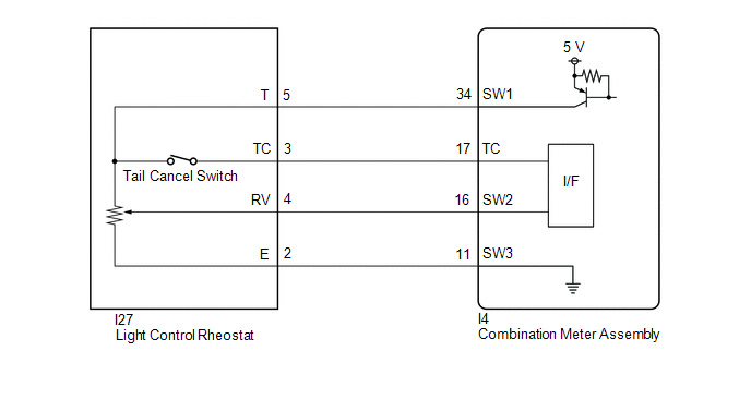
The combination meter assembly receives signals from the light control rheostat to adjust the illumination of the combination meter assembly. The combination meter assembly sets the illumination level based on the user operation of the light control rheostat.
HINT:
The tail cancel switch is built into the light control rheostat. When the light control rheostat is moved to the highest position, the tail cancel switch will turn on and the meter illumination will be set to maximum brightness.
WIRING DIAGRAM

CAUTION / NOTICE / HINT
NOTICE:
When replacing the combination meter assembly, always replace it with a new one. If a combination meter assembly which was installed to another vehicle is used, the information stored in it will not match the information from the vehicle and a DTC may be stored.
PROCEDURE
|
1. |
CHECK SYMPTOMS |
(a) Ask the customer about the problem symptoms.
|
Result |
Proceed to |
|---|---|
|
Meter illumination does not change when operating the light control rheostat |
A |
|
Tail cancel switch malfunction |
B |
| B |

|
|
|
2. |
READ VALUE USING TECHSTREAM |
(a) Connect the Techstream to the DLC3.
(b) Turn the engine switch on (IG).
(c) Turn the Techstream on.
(d) Enter the following menus: Body Electrical / Combination Meter / Data List.
(e) Read the Data List according to the display on the Techstream.
Body Electrical > Combination Meter > Data List
|
Tester Display |
Measurement Item |
Range |
Normal Condition |
Diagnostic Note |
|---|---|---|---|---|
|
Rheostat value |
Light control rheostat input |
Min.: 0.00%, Max.: 100.01% or Unset |
Increases from 0 to 100 as light control rheostat turned from low to high |
"Unset" is displayed when the light control rheostat is moved to the highest position (tail cancel switch is turned on). |
Body Electrical > Combination Meter > Data List
|
Tester Display |
|---|
|
Rheostat value |
OK:
The value displayed on the Techstream changes according to the actual light control rheostat operation.
| OK |

|
|
|
3. |
INSPECT LIGHT CONTROL RHEOSTAT |
(a) Remove the light control rheostat.
(b) Inspect the light control rheostat.
| NG |

|
|
|
4. |
CHECK HARNESS AND CONNECTOR (LIGHT CONTROL RHEOSTAT - COMBINATION METER ASSEMBLY) |
(a) Disconnect the I27 light control rheostat connector.
(b) Disconnect the I4 combination meter assembly connector.
(c) Measure the resistance according to the value(s) in the table below.
Standard Resistance:
|
Tester Connection |
Condition |
Specified Condition |
|---|---|---|
|
I27-5 (T) - I4-34 (SW1) |
Always |
Below 1 Ω |
|
I27-4 (RV) - I4-16 (SW2) |
Always |
Below 1 Ω |
|
I27-2 (E) - I4-11 (SW3) |
Always |
Below 1 Ω |
|
I27-5 (T) or I4-34 (SW1) - Body ground |
Always |
10 kΩ or higher |
|
I27-4 (RV) or I4-16 (SW2) - Body ground |
Always |
10 kΩ or higher |
| OK |

|
| NG |

|
REPAIR OR REPLACE HARNESS OR CONNECTOR |
|
5. |
READ VALUE USING TECHSTREAM |
(a) Connect the Techstream to the DLC3.
(b) Turn the engine switch on (IG).
(c) Turn the Techstream on.
(d) Enter the following menus: Body Electrical / Combination Meter / Data List.
(e) Read the Data List according to the display on the Techstream.
Body Electrical > Combination Meter > Data List
|
Tester Display |
Measurement Item |
Range |
Normal Condition |
Diagnostic Note |
|---|---|---|---|---|
|
Meter Day Mode Switch |
Tail cancel switch (Light control rheostat) |
OFF or ON |
OFF: Tail cancel switch off ON: Tail cancel switch on |
When the light control rheostat is moved to the highest position, the tail cancel switch will turn on. |
Body Electrical > Combination Meter > Data List
|
Tester Display |
|---|
|
Meter Day Mode Switch |
OK:
Normal conditions listed above are displayed.
| OK |

|
|
|
6. |
INSPECT LIGHT CONTROL RHEOSTAT |
(a) Remove the light control rheostat.
(b) Inspect the light control rheostat.
| NG |

|
|
|
7. |
CHECK HARNESS AND CONNECTOR (LIGHT CONTROL RHEOSTAT - COMBINATION METER ASSEMBLY) |
(a) Disconnect the I27 light control rheostat connector.
(b) Disconnect the I4 combination meter assembly connector.
(c) Measure the resistance according to the value(s) in the table below.
Standard Resistance:
|
Tester Connection |
Condition |
Specified Condition |
|---|---|---|
|
I27-5 (T) - I4-34 (SW1) |
Always |
Below 1 Ω |
|
I27-3 (TC) - I4-17 (TC) |
Always |
Below 1 Ω |
|
I27-5 (T) or I4-34 (SW1) - Body ground |
Always |
10 kΩ or higher |
|
I27-3 (TC) or I4-17 (TC) - Body ground |
Always |
10 kΩ or higher |
| OK |

|
| NG |

|
REPAIR OR REPLACE HARNESS OR CONNECTOR |
|
|
|

![2019 MY Corolla Corolla Hatchback Corolla HV GR Corolla [06/2018 - 01/2019]; METER / GAUGE / DISPLAY: COMBINATION METER: REMOVAL](/t3Portal/stylegraphics/info.gif)