| Last Modified: 06-05-2026 | 6.11:8.1.0 | Doc ID: RM0000003TPGAQ7 |
| Model Year Start: 2026 | Model: GR Corolla | Prod Date Range: [03/2026 - ] |
| Title: SUPPLEMENTAL RESTRAINT SYSTEMS: OCCUPANT CLASSIFICATION SYSTEM (for TMC, TMUK Made): B179316; Load Sensor for Occupant Detection System Circuit Voltage Below Threshold; 2026 MY GR Corolla Corolla Corolla Hatchback Corolla HV [03/2026 - ] | ||
|
DTC |
B179316 |
Load Sensor for Occupant Detection System Circuit Voltage Below Threshold |
DESCRIPTION
|
DTC No. |
Detection Item |
DTC Detection Condition |
Trouble Area |
|---|---|---|---|
|
B179316 |
Load Sensor for Occupant Detection System Circuit Voltage Below Threshold |
When the detections voltage value below specified value before supplying power to the sensor. |
|
WIRING DIAGRAM
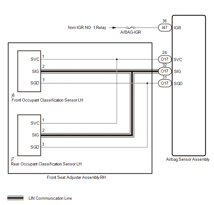
CAUTION / NOTICE / HINT
NOTICE:
-
After the ignition switch is turned off, there may be a waiting time before disconnecting the negative (-) auxiliary battery terminal.
Click here
![2023 - 2026 MY GR Corolla Corolla Corolla Hatchback Corolla HV [09/2022 - ]; SETUP: WHEN DISCONNECTING OR RECONNECTING BATTERY TERMINAL: BEFORE DISCONNECTING BATTERY](/t3Portal/stylegraphics/info.gif)
HINT:
When disconnecting and reconnecting the auxiliary battery, there is an automatic learning function that completes learning when the respective system is used.
Click here
-
After replacing the airbag sensor assembly or front seat adjuster assembly RH, refer to work procedure.
Click here
- Inspect the fuses for circuits related to this system before performing the following procedure.
HINT:
- If it is difficult to perform troubleshooting (wire harness inspection), remove the front passenger seat installation bolts to see under the seat cushion.
- In the above case, lift and hold the seat so that it does not fall down. Hold the seat only as necessary because holding the seat for a long period of time may cause seat rail deformation.
PROCEDURE
|
1. |
CHECK CONNECTION OF CONNECTORS |
(a) Turn the ignition switch off.
(b) Disconnect the cable from the negative (-) auxiliary battery terminal, and wait for at least 60 seconds.
(c) Check that the connectors are properly connected to the airbag sensor assembly and front seat adjuster assembly RH.
OK:
The connectors are properly connected.
| NG |

|
CONNECT CONNECTORS PROPERLY |
|

|
2. |
CHECK CONNECTORS |
|
(a) Disconnect the airbag sensor assembly connector. |
|
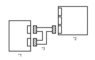
(b) Disconnect the front seat adjuster assembly RH connector.
(c) Check that the terminals of the connectors are not deformed or damaged.
OK:
The terminals are not deformed or damaged.
| NG |
|
REPAIR OR REPLACE HARNESS OR CONNECTOR |
|
|
3. |
CHECK HARNESS AND CONNECTOR (AIRBAG SENSOR ASSEMBLY - AUXILIARY BATTERY) |
|
(a) Disconnect the airbag sensor assembly connector. |
|
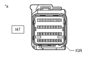
(b) Connect the cable to the negative (-) auxiliary battery terminal, and wait for at least 2 seconds.
(c) Turn the ignition switch to ON.
(d) Operate all components of the electrical systems (defogger, wipers, headlights, heater blower, etc.).
(e) Measure the voltage according to the value(s) in the table below.
Standard Voltage
|
Tester Connection |
Condition |
Specified Condition |
|---|---|---|
|
I47-36 (IGR) - Body ground |
Ignition switch ON |
8 to 16 V |
| NG |
|
REPAIR OR REPLACE HARNESS OR CONNECTOR |
|
|
4. |
CHECK HARNESS AND CONNECTOR (AIRBAG SENSOR ASSEMBLY - FRONT SEAT ADJUSTER ASSEMBLY RH) |
|
(a) Measure the resistance according to the value(s) in the table below. Standard Resistance
|
|
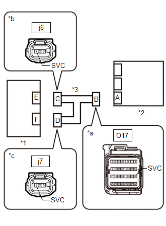
| NG |
|
REPAIR OR REPLACE HARNESS OR CONNECTOR |
|
|
5. |
CHECK AIRBAG SENSOR ASSEMBLY |
|
(a) Turn the ignition switch off. |
|
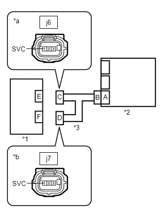
(b) Disconnect the cable from the negative (-) auxiliary battery terminal, and wait for at least 60 seconds.
(c) Connect the connector to the airbag sensor assembly.
(d) Connect the cable to the negative (-) auxiliary battery terminal, and wait for at least 2 seconds.
(e) Measure the voltage according to the value(s) in the table below.
Standard Voltage
|
Tester Connection |
Condition |
Specified Condition |
|---|---|---|
|
j6-1 (SVC) - Body ground |
Ignition switch ON |
6.2 V or higher |
|
j7-1 (SVC) - Body ground |
Ignition switch ON |
6.2 V or higher |
|
|

|

|