| Last Modified: 06-05-2026 | 6.11:8.1.0 | Doc ID: RM0000003TPDEVX |
| Model Year Start: 2026 | Model: GR Corolla | Prod Date Range: [08/2025 - ] |
| Title: METER / GAUGE / DISPLAY: METER / GAUGE SYSTEM (for 12.3 Inch Display): Steering Pad Switch Circuit; 2026 MY GR Corolla Corolla Corolla Hatchback Corolla HV [08/2025 - ] | ||
|
Steering Pad Switch Circuit |
DESCRIPTION
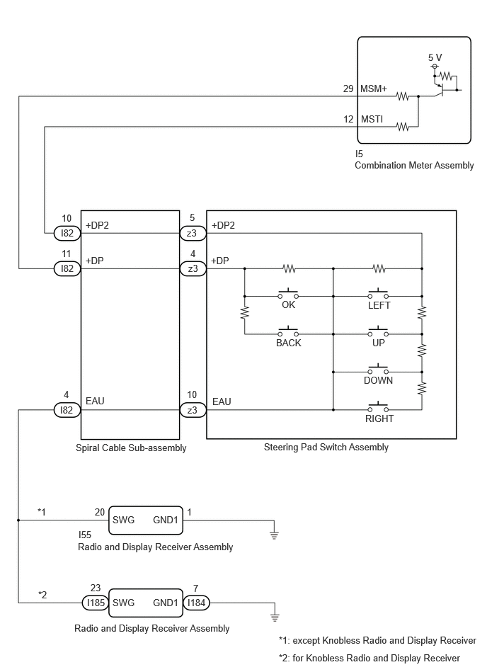
The combination meter assembly and steering pad switch assembly are connected via direct line. The multi-information display in the combination meter assembly is operated using the switches of the steering pad switch assembly.
WIRING DIAGRAM
CAUTION / NOTICE / HINT
NOTICE:
- When replacing the combination meter assembly, always replace it with a new one. If a combination meter assembly which was installed to another vehicle is used, the information stored in it will not match the information from the vehicle and a DTC may be stored.
-
When replacing the combination meter assembly, update the ECU security key.
Click here
![2023 - 2026 MY GR Corolla Corolla Corolla Hatchback Corolla HV [09/2022 - ]; SETUP: WHEN REPLACING OR REMOVING/INSTALLING PARTS: UPDATE ECU SECURITY KEY](/t3Portal/stylegraphics/info.gif)
PROCEDURE
|
1. |
INSPECT STEERING PAD SWITCH ASSEMBLY |
except G16E-GTS: Click here
for G16E-GTS: Click here
| NG |

|
REPLACE STEERING PAD SWITCH ASSEMBLY
except G16E-GTS: Click here
for G16E-GTS: Click here
|
|

|
2. |
INSPECT SPIRAL CABLE SUB-ASSEMBLY |
Click here
| NG |
|
|
|
3. |
CHECK HARNESS AND CONNECTOR (SPIRAL CABLE SUB-ASSEMBLY - COMBINATION METER ASSEMBLY) |
(a) Disconnect the I5 combination meter assembly connector.
(b) Measure the resistance according to the value(s) in the table below.
Standard Resistance
|
Tester Connection |
Condition |
Specified Condition |
|---|---|---|
|
I82-11 (+DP) - I5-29 (MSM+) |
Always |
Below 1 Ω |
|
I82-10 (+DP2) - I5-12 (MSTI) |
Always |
Below 1 Ω |
|
I82-11 (+DP) or I5-29 (MSM+) - Body ground |
Always |
10 kΩ or higher |
|
I82-10 (+DP2) or I5-12 (MSTI) - Body ground |
Always |
10 kΩ or higher |
| NG |
|
REPAIR OR REPLACE HARNESS OR CONNECTOR |
|
|
4. |
CHECK COMBINATION METER ASSEMBLY (OUTPUT VOLTAGE) |
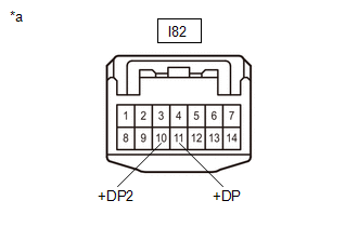
|
*a |
Front view of wire harness connector (to Spiral Cable Sub-assembly) |
(a) Connect the I5 combination meter assembly connector.
(b) Measure the voltage according to the value(s) in the table below.
Standard Voltage
|
Tester Connection |
Condition |
Specified Condition |
|---|---|---|
|
I82-11 (+DP) - Body ground |
Ignition switch ON |
4.8 to 5.2 V |
|
I82-10 (+DP2) - Body ground |
Ignition switch ON |
4.8 to 5.2 V |
| NG |
|
|
|
5. |
CONFIRM MODEL |
(a) Choose the model to be inspected.
Result
|
Result |
Proceed to |
|---|---|
|
except Knobless Radio and Display Receiver |
A |
|
for Knobless Radio and Display Receiver |
B |
| B |
|
|
|
6. |
CHECK HARNESS AND CONNECTOR (RADIO AND DISPLAY RECEIVER ASSEMBLY - SPIRAL CABLE SUB-ASSEMBLY AND BODY GROUND) |
(a) Disconnect the I55 radio and display receiver assembly connector.
(b) Measure the resistance according to the value(s) in the table below.
Standard Resistance
|
Tester Connection |
Condition |
Specified Condition |
|---|---|---|
|
I55-20 (SWG) - I82-4 (EAU) |
Always |
Below 1 Ω |
|
I55-1 (GND1) - Body ground |
Always |
Below 1 Ω |
| OK |
|
| NG |
|
REPAIR OR REPLACE HARNESS OR CONNECTOR |
|
7. |
CHECK HARNESS AND CONNECTOR (RADIO AND DISPLAY RECEIVER ASSEMBLY - SPIRAL CABLE SUB-ASSEMBLY AND BODY GROUND) |
(a) Disconnect the I184 and I185 radio and display receiver assembly connectors.
(b) Measure the resistance according to the value(s) in the table below.
Standard Resistance
|
Tester Connection |
Condition |
Specified Condition |
|---|---|---|
|
I185-23 (SWG) - I82-4 (EAU) |
Always |
Below 1 Ω |
|
I184-7 (GND1) - Body ground |
Always |
Below 1 Ω |
|
|

|

|