| Last Modified: 08-22-2025 | 6.11:8.1.0 | Doc ID: RM0000003TPDEVL |
| Model Year Start: 2026 | Model: GR Corolla | Prod Date Range: [08/2025 - ] |
| Title: METER / GAUGE / DISPLAY: METER / GAUGE SYSTEM (for 12.3 Inch Display): B150013,B150113; Fuel Sender Circuit Open; 2026 MY Corolla Corolla Hatchback Corolla HV GR Corolla [08/2025 - ] | ||
|
DTC |
B150013 |
Fuel Sender Circuit Open |
|
DTC |
B150113 |
Sub Fuel Sender Circuit Open |
DESCRIPTION
except G16E-GTS
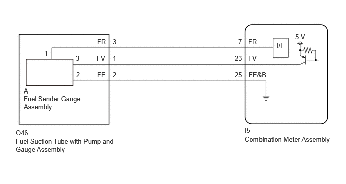
- The fuel sender gauge assembly is connected to the combination meter assembly via direct line. If there is an open or short in the direct line, the combination meter assembly stores DTC B150013.
for G16E-GTS
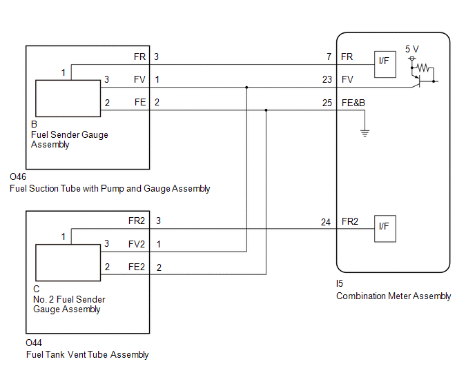
- The fuel sender gauge assembly and No. 2 fuel sender gauge assembly are connected to the combination meter assembly via direct line. If there is an open or short in the direct line, the combination meter assembly stores DTC B150013 or B150113.
|
DTC No. |
Detection Item |
DTC Detection Condition |
Trouble Area |
|---|---|---|---|
|
B150013 |
Fuel Sender Circuit Open |
Diagnosis Condition:
Malfunction Status:
Malfunction Time:
|
|
|
B150113 |
Sub Fuel Sender Circuit Open |
Diagnosis Condition:
Malfunction Status:
Malfunction Time:
|
|
WIRING DIAGRAM
except G16E-GTS
for G16E-GTS
CAUTION / NOTICE / HINT
NOTICE:
- When replacing the combination meter assembly, always replace it with a new one. If a combination meter assembly which was installed to another vehicle is used, the information stored in it will not match the information from the vehicle and a DTC may be stored.
-
When replacing the combination meter assembly, update the ECU security key.
Click here
![2023 - 2026 MY Corolla Corolla Hatchback Corolla HV GR Corolla [09/2022 - ]; SETUP: WHEN REPLACING OR REMOVING/INSTALLING PARTS: UPDATE ECU SECURITY KEY](/t3Portal/stylegraphics/info.gif)
PROCEDURE
|
1. |
CONFIRM MODEL |
(a) Choose the model to be inspected.
|
Result |
Proceed to |
|---|---|
|
except G16E-GTS |
A |
|
for G16E-GTS |
B |
| B |

|
|

|
2. |
CONFIRM MODEL |
(a) Choose the model to be inspected.
|
Result |
Proceed to |
|---|---|
|
for HV Model |
A |
|
for Gasoline Model |
B |
| B |
|
|
|
3. |
READ VALUE USING GTS |
(a) Read the Data List according to the display on the GTS.
Body Electrical > Combination Meter > Data List
|
Tester Display |
Measurement Item |
Range |
Normal Condition |
Diagnostic Note |
|---|---|---|---|---|
|
Fuel Input |
Fuel level gauge output |
Min.: 0.00 L, Max.: 655.35 L or Unset |
for 4WD
except 4WD
|
- |
Body Electrical > Combination Meter > Data List
|
Tester Display |
|---|
|
Fuel Input |
|
Result |
Proceed to |
|---|---|
|
Fuel level data can be displayed on the GTS |
A |
|
Fuel level data cannot be displayed on the GTS |
B |
| A |
|
|
|
4. |
INSPECT FUEL SENDER GAUGE ASSEMBLY |
w/ Canister Pump Module: Click here
w/o Canister Pump Module: Click here
| NG |
|
REPLACE FUEL SENDER GAUGE ASSEMBLY w/ Canister Pump Module: Click here
w/o Canister Pump Module: Click here
|
|
|
5. |
INSPECT FUEL SUCTION TUBE WITH PUMP AND GAUGE ASSEMBLY |
|
(a) Measure the resistance according to the value(s) in the table below. Standard Resistance:
|
|

| NG |
|
REPLACE FUEL SUCTION TUBE WITH PUMP AND GAUGE ASSEMBLY w/ Canister Pump Module: Click here
w/o Canister Pump Module: Click here
|
|
|
6. |
CHECK HARNESS AND CONNECTOR (FUEL SUCTION TUBE WITH PUMP AND GAUGE ASSEMBLY - COMBINATION METER ASSEMBLY) |
(a) Disconnect the I5 combination meter assembly connector.
(b) Measure the resistance according to the value(s) in the table below.
Standard Resistance:
|
Tester Connection |
Condition |
Specified Condition |
|---|---|---|
|
O46-3 (FR) - I5-7 (FR) |
Always |
Below 1 Ω |
|
O46-2 (FE) - I5-25 (FE&B) |
Always |
Below 1 Ω |
|
O46-1 (FV) - I5-23 (FV) |
Always |
Below 1 Ω |
|
O46-3 (FR) or I5-7 (FR) - Body ground |
Always |
10 kΩ or higher |
|
O46-1 (FV) or I5-23 (FV) - Body ground |
Always |
10 kΩ or higher |
| OK |
|
| NG |
|
REPAIR OR REPLACE HARNESS OR CONNECTOR |
|
7. |
READ VALUE USING GTS |
(a) Read the Data List according to the display on the GTS.
Body Electrical > Combination Meter > Data List
|
Tester Display |
Measurement Item |
Range |
Normal Condition |
Diagnostic Note |
|---|---|---|---|---|
|
Fuel Input |
Fuel level gauge output |
Min.: 0.00 L, Max.: 655.35 L or Unset |
for 50liter Tank Model
for 47liter Tank Model
|
- |
Body Electrical > Combination Meter > Data List
|
Tester Display |
|---|
|
Fuel Input |
|
Result |
Proceed to |
|---|---|
|
Fuel level data can be displayed on the GTS |
A |
|
Fuel level data cannot be displayed on the GTS |
B |
| A |
|
|
|
8. |
INSPECT FUEL SENDER GAUGE ASSEMBLY |
w/o Canister Pump Module (for Double Wishbone Type Suspension): Click here
w/ Canister Pump Module (for Double Wishbone Type Suspension): Click here
w/o Canister Pump Module (for Torsion Beam Type Suspension): Click here
w/ Canister Pump Module (for Torsion Beam Type Suspension): Click here
| NG |
|
REPLACE FUEL SENDER GAUGE ASSEMBLY w/o Canister Pump Module (for Double Wishbone Type Suspension): Click here
w/ Canister Pump Module (for Double Wishbone Type Suspension): Click here
w/o Canister Pump Module (for Torsion Beam Type Suspension): Click here
w/ Canister Pump Module (for Torsion Beam Type Suspension): Click here
|
|
|
9. |
INSPECT FUEL SUCTION TUBE WITH PUMP AND GAUGE ASSEMBLY |
|
(a) Measure the resistance according to the value(s) in the table below. Standard Resistance:
|
|
| NG |
|
REPLACE FUEL SUCTION TUBE WITH PUMP AND GAUGE ASSEMBLY w/o Canister Pump Module (for Double Wishbone Type Suspension): Click here
w/ Canister Pump Module (for Double Wishbone Type Suspension): Click here
w/o Canister Pump Module (for Torsion Beam Type Suspension): Click here
w/ Canister Pump Module (for Torsion Beam Type Suspension): Click here
|
|
|
10. |
CHECK HARNESS AND CONNECTOR (FUEL SUCTION TUBE WITH PUMP AND GAUGE ASSEMBLY - COMBINATION METER ASSEMBLY) |
(a) Disconnect the I5 combination meter assembly connector.
(b) Measure the resistance according to the value(s) in the table below.
Standard Resistance:
|
Tester Connection |
Condition |
Specified Condition |
|---|---|---|
|
O46-3 (FR) - I5-7 (FR) |
Always |
Below 1 Ω |
|
O46-2 (FE) - I5-25 (FE&B) |
Always |
Below 1 Ω |
|
O46-1 (FV) - I5-23 (FV) |
Always |
Below 1 Ω |
|
O46-3 (FR) or I5-7 (FR) - Body ground |
Always |
10 kΩ or higher |
|
O46-1 (FV) or I5-23 (FV) - Body ground |
Always |
10 kΩ or higher |
| OK |
|
| NG |
|
REPAIR OR REPLACE HARNESS OR CONNECTOR |
|
11. |
CHECK FOR DTC |
(a) Check for DTCs.
Body Electrical > Combination Meter > Trouble Codes
|
Result |
Proceed to |
|---|---|
|
Only B150013 is output |
A |
|
Only B150113 is output |
B |
|
B150013 and B150113 are output |
C |
| B |
|
| C |
|
|
|
12. |
READ VALUE USING GTS |
(a) Read the Data List according to the display on the GTS.
Body Electrical > Combination Meter > Data List
|
Tester Display |
Measurement Item |
Range |
Normal Condition |
Diagnostic Note |
|---|---|---|---|---|
|
Fuel Input |
Fuel level gauge output |
Min.: 0.00 L, Max.: 655.35 L or Unset |
|
- |
Body Electrical > Combination Meter > Data List
|
Tester Display |
|---|
|
Fuel Input |
|
Result |
Proceed to |
|---|---|
|
Fuel level data can be displayed on the GTS |
A |
|
Fuel level data cannot be displayed on the GTS |
B |
| A |
|
|
|
13. |
INSPECT FUEL SENDER GAUGE ASSEMBLY |
Click here
| NG |
|
|
|
14. |
INSPECT FUEL SUCTION TUBE WITH PUMP AND GAUGE ASSEMBLY |
|
(a) Measure the resistance according to the value(s) in the table below. Standard Resistance:
|
|
| NG |
|
|
|
15. |
CHECK HARNESS AND CONNECTOR (FUEL SUCTION TUBE WITH PUMP AND GAUGE ASSEMBLY - COMBINATION METER ASSEMBLY) |
(a) Disconnect the I5 combination meter assembly connector.
(b) Measure the resistance according to the value(s) in the table below.
Standard Resistance:
|
Tester Connection |
Condition |
Specified Condition |
|---|---|---|
|
O46-3 (FR) - I5-7 (FR) |
Always |
Below 1 Ω |
|
O46-2 (FE) - I5-25 (FE&B) |
Always |
Below 1 Ω |
|
O46-1 (FV) - I5-23 (FV) |
Always |
Below 1 Ω |
|
O46-1 (FV) or I5-23 (FV) - Body ground |
Always |
10 kΩ or higher |
| OK |
|
| NG |
|
REPAIR OR REPLACE HARNESS OR CONNECTOR |
|
16. |
READ VALUE USING GTS |
(a) Read the Data List according to the display on the GTS.
Body Electrical > Combination Meter > Data List
|
Tester Display |
Measurement Item |
Range |
Normal Condition |
Diagnostic Note |
|---|---|---|---|---|
|
Sub Fuel Input |
Fuel level input |
Min.: 0 L, Max.: 655.35 L or Unset |
|
The detected value of the No. 2 fuel sender gauge assembly is displayed. |
Body Electrical > Combination Meter > Data List
|
Tester Display |
|---|
|
Sub Fuel Input |
|
Result |
Proceed to |
|---|---|
|
Fuel level data can be displayed on the GTS |
A |
|
Fuel level data cannot be displayed on the GTS |
B |
| A |
|
|
|
17. |
INSPECT NO. 2 FUEL SENDER GAUGE ASSEMBLY |
Click here
| NG |
|
|
|
18. |
INSPECT FUEL TANK VENT TUBE ASSEMBLY |
|
(a) Measure the resistance according to the value(s) in the table below. Standard Resistance:
|
|
| NG |
|
|
|
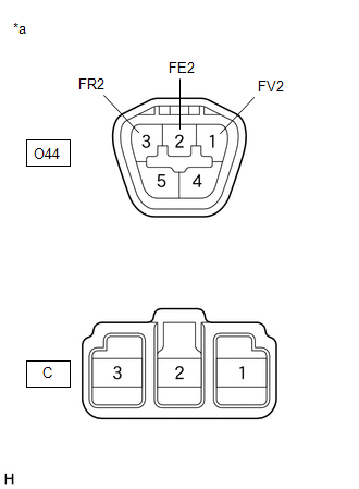
19. |
CHECK HARNESS AND CONNECTOR (FUEL TANK VENT TUBE ASSEMBLY - COMBINATION METER ASSEMBLY) |
(a) Disconnect the I5 combination meter assembly connector.
(b) Measure the resistance according to the value(s) in the table below.
Standard Resistance:
|
Tester Connection |
Condition |
Specified Condition |
|---|---|---|
|
O44-3 (FR2) - I5-24 (FR2) |
Always |
Below 1 Ω |
|
O44-1 (FV2) - I5-23 (FV) |
Always |
Below 1 Ω |
|
O44-2 (FE2) - I5-25 (FE&B) |
Always |
Below 1 Ω |
|
O44-3 (FR2) or I5-24 (FR2) - Body ground |
Always |
10 kΩ or higher |
| OK |
|
| NG |
|
REPAIR OR REPLACE HARNESS OR CONNECTOR |
|
20. |
READ VALUE USING GTS |
(a) Read the Data List according to the display on the GTS.
Body Electrical > Combination Meter > Data List
|
Tester Display |
Measurement Item |
Range |
Normal Condition |
Diagnostic Note |
|---|---|---|---|---|
|
Fuel Input |
Fuel level gauge output |
Min.: 0.00 L, Max.: 655.35 L or Unset |
|
The detected value of the fuel sender gauge assembly is displayed. |
|
Sub Fuel Input |
Fuel level input |
Min.: 0 L, Max.: 655.35 L or Unset |
|
The detected value of the No. 2 fuel sender gauge assembly is displayed. |
Body Electrical > Combination Meter > Data List
|
Tester Display |
|---|
|
Fuel Input |
|
Sub Fuel Input |
|
Result |
Proceed to |
|---|---|
|
Fuel level data can be displayed on the GTS |
A |
|
Fuel level data cannot be displayed on the GTS |
B |
| A |
|
|
|
21. |
INSPECT FUEL SENDER GAUGE ASSEMBLY |
Click here
| NG |
|
|
|
22. |
INSPECT FUEL SUCTION TUBE WITH PUMP AND GAUGE ASSEMBLY |
|
(a) Measure the resistance according to the value(s) in the table below. Standard Resistance:
|
|

| NG |
|
|
|
23. |
INSPECT NO. 2 FUEL SENDER GAUGE ASSEMBLY |
Click here
| NG |
|
|
|
24. |
INSPECT FUEL TANK VENT TUBE ASSEMBLY |
|
(a) Measure the resistance according to the value(s) in the table below. Standard Resistance:
|
|

| NG |
|
|
|
25. |
CHECK HARNESS AND CONNECTOR (FUEL SUCTION TUBE WITH PUMP AND GAUGE ASSEMBLY AND FUEL TANK VENT TUBE ASSEMBLY - COMBINATION METER ASSEMBLY) |
(a) Disconnect the I5 combination meter assembly connector.
(b) Measure the resistance according to the value(s) in the table below.
Standard Resistance:
|
Tester Connection |
Condition |
Specified Condition |
|---|---|---|
|
O46-1 (FV) or O44-1 (FV2) - I5-23 (FV) |
Always |
Below 1 Ω |
|
O46-2 (FE) or O44-2 (FE2) - I5-25 (FE&B) |
Always |
Below 1 Ω |
|
O46-1 (FV), O44-1 (FV2) or I5-23 (FV) - Body ground |
Always |
10 kΩ or higher |
|
O46-3 (FR) or I5-7 (FR) - Body ground |
Always |
10 kΩ or higher |
|
O44-3 (FR2) or I5-24 (FR2) - Body ground |
Always |
10 kΩ or higher |
| OK |
|
| NG |
|
REPAIR OR REPLACE HARNESS OR CONNECTOR |
|
|
|