| Last Modified: 08-22-2025 | 6.11:8.1.0 | Doc ID: RM0000003TPDD93 |
| Model Year Start: 2026 | Model: GR Corolla | Prod Date Range: [08/2025 - ] |
| Title: POWER OUTLETS (INT): WIRELESS CHARGING SYSTEM (for Type A): Wireless Charger Illumination Circuit; 2026 MY Corolla Corolla Hatchback Corolla HV GR Corolla [08/2025 - ] | ||
|
Wireless Charger Illumination Circuit |
DESCRIPTION
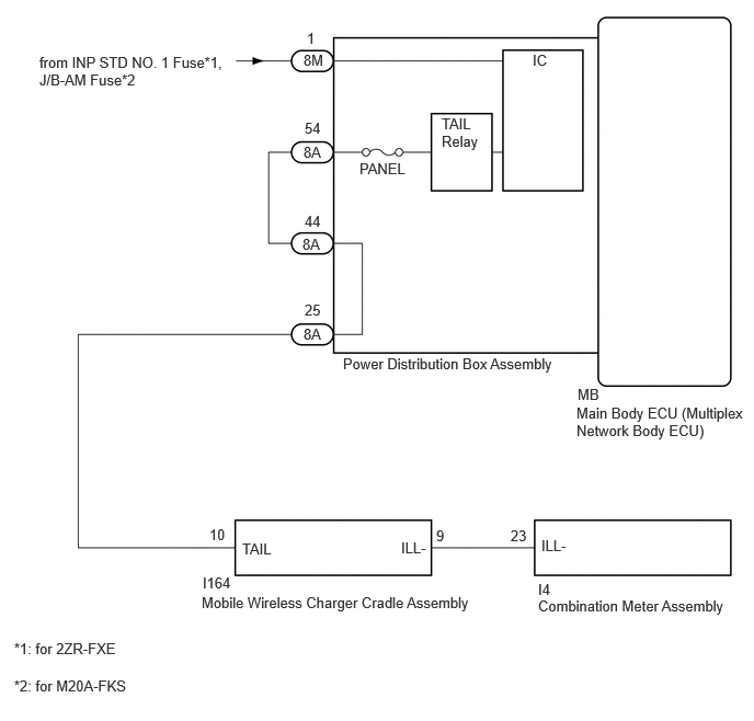
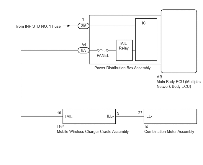
When the taillight on, this circuit sends an illumination signal to the mobile wireless charger cradle assembly.
WIRING DIAGRAM
except TMC Made (G16E-GTS)
for TMC Made (G16E-GTS)
CAUTION / NOTICE / HINT
NOTICE:
Inspect the fuses for circuits related to this system before performing the following procedure.
PROCEDURE
|
1. |
CHECK HARNESS AND CONNECTOR (ILLUMINATION SIGNAL) |
(a) Disconnect the I164 mobile wireless charger cradle assembly connector.
(b) Measure the voltage according to the value(s) in the table below.
Standard Voltage:
|
Tester Connection |
Condition |
Specified Condition |
|---|---|---|
|
I164-10 (TAIL) - Body ground |
Taillight off |
Below 1 V |
|
Engine switch off, taillight on |
11 to 14 V |
| NG |

|
REPAIR OR REPLACE HARNESS OR CONNECTOR |
|

|
2. |
CHECK HARNESS AND CONNECTOR (COMBINATION METER ASSEMBLY - MOBILE WIRELESS CHARGER CRADLE ASSEMBLY) |
(a) Disconnect the I4 combination meter assembly connector.
(b) Measure the resistance according to the value(s) in the table below.
Standard Resistance:
|
Tester Connection |
Condition |
Specified Condition |
|---|---|---|
|
I4-23 (ILL-) - I164-9 (ILL-) |
Always |
Below 1 Ω |
|
I4-23 (ILL-) or I164-9 (ILL-) - Body ground |
Always |
10 kΩ or higher |
| OK |
|
| NG |
|
REPAIR OR REPLACE HARNESS OR CONNECTOR |
|
|
|