| Last Modified: 08-22-2025 | 6.11:8.1.0 | Doc ID: RM0000003TPCZX4 |
| Model Year Start: 2025 | Model: GR Corolla | Prod Date Range: [09/2024 - ] |
| Title: BRAKE CONTROL / DYNAMIC CONTROL SYSTEMS: VSC OFF SWITCH: INSPECTION; 2025 - 2026 MY Corolla Corolla Hatchback Corolla HV GR Corolla [09/2024 - ] | ||
INSPECTION
PROCEDURE
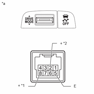
1. INSPECT VSC OFF SWITCH (COMBINATION SWITCH ASSEMBLY) (for Shift Panel)
(a) for Type A:
|
(1) Make sure that there is no looseness in the locking part and the connecting part of the connector. OK: The connector is securely connected. |
|
(2) Disconnect the VSC OFF switch (combination switch assembly) connector.
(3) Check both the connector case and the terminals for deformation and corrosion.
OK:
No deformation or corrosion.
(4) Measure the resistance according to the value(s) in the table below.
Standard Resistance:
|
Tester Connection |
Condition |
Specified Condition |
|---|---|---|
|
*1: except Manual Transmission / Transaxle
*2: for Manual Transmission / Transaxle |
||
|
8 (+) - 5 (E) *1 |
Switch pushed |
Below 50 Ω |
|
8 (+) - 5 (E) *1 |
Switch not pushed |
10 kΩ or higher |
|
2 (+) - 5 (E) *2 |
Switch pushed |
Below 50 Ω |
|
2 (+) - 5 (E) *2 |
Switch not pushed |
10 kΩ or higher |
HINT:
If the result is not as specified, replace the VSC OFF switch (combination switch assembly).
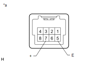
(b) except Type A:
|
(1) Make sure that there is no looseness in the locking part and the connecting part of the connector. OK: The connector is securely connected. |
|
(2) Disconnect the VSC OFF switch (combination switch assembly) connector.
(3) Check both the connector case and the terminals for deformation and corrosion.
OK:
No deformation or corrosion.
(4) Measure the resistance according to the value(s) in the table below.
Standard Resistance:
|
Tester Connection |
Condition |
Specified Condition |
|---|---|---|
|
7 (+) - 5 (E) |
Switch pushed |
Below 50 Ω |
|
7 (+) - 5 (E) |
Switch not pushed |
10 kΩ or higher |
HINT:
If the result is not as specified, replace the VSC OFF switch (combination switch assembly).
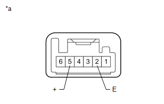
2. INSPECT VSC OFF SWITCH (for Instrument Panel)
|
(a) Make sure that there is no looseness in the locking part and the connecting part of the connector. OK: The connector is securely connected. |
|
(b) Disconnect the VSC OFF switch connector.
(c) Check both the connector case and the terminals for deformation and corrosion.
OK:
No deformation or corrosion.
(d) Measure the resistance according to the value(s) in the table below.
Standard Resistance:
|
Tester Connection |
Condition |
Specified Condition |
|---|---|---|
|
5 (+) - 2 (E) |
Switch pushed |
Below 1 Ω |
|
5 (+) - 2 (E) |
Switch not pushed |
10 kΩ or higher |
HINT:
If the result is not as specified, replace the VSC OFF switch.
|
|
|