| Last Modified: 08-22-2025 | 6.11:8.1.0 | Doc ID: RM0000003TPCPNW |
| Model Year Start: 2024 | Model: GR Corolla | Prod Date Range: [08/2023 - ] |
| Title: BRAKE CONTROL / DYNAMIC CONTROL SYSTEMS: ELECTRONICALLY CONTROLLED BRAKE SYSTEM (for Gasoline Model with Electric Parking Brake System): C117A49; Brake System Control Module "A" System Voltage Line Internal Electronic Failure; 2024 - 2026 MY Corolla Corolla Hatchback GR Corolla [08/2023 - ] | ||
|
DTC |
C117A49 |
Brake System Control Module "A" System Voltage Line Internal Electronic Failure |
DESCRIPTION
If a malfunction is detected in the power supply circuit, the skid control ECU (brake actuator assembly) stores this DTC and the fail-safe function prohibits ABS operation.
This DTC is stored when the +BS terminal voltage meets one of the DTC detection conditions due to a malfunction in the power supply or charging circuit such as the battery or alternator circuit, etc.
The DTC is cleared when the +BS terminal voltage returns to normal.
|
DTC No. |
Detection Item |
DTC Detection Condition |
Trouble Area |
MIL |
Note |
|---|---|---|---|---|---|
|
C117A49 |
Brake System Control Module "A" System Voltage Line Internal Electronic Failure |
The vehicle speed is 15 km/h (9 mph) or more and the +BS terminal voltage is 9.6 V or more, the skid control ECU (brake actuator assembly) turns on more than one valve at the same time within a short period of time and the valve relay supply voltage drop exceeds the threshold.* |
|
Does not come on |
- |
*: The skid control ECU (brake actuator assembly) monitors the resistance of the power source line at the +BS terminal. A malfunction is detected when an abnormality occurs in the +BS terminal wire harness or its connection and the skid control ECU (brake actuator assembly) determines that the wiring resistance at the +BS terminal exceeds the standard resistance.
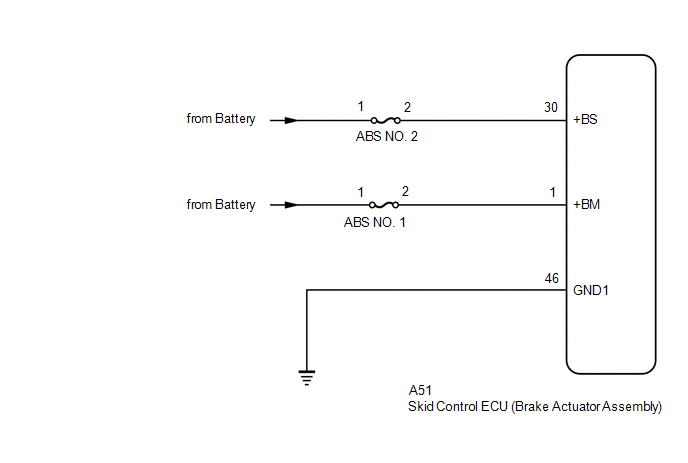
WIRING DIAGRAM
CAUTION / NOTICE / HINT
NOTICE:
- Inspect the fuses for circuits related to this system before performing the following procedure.
-
Before performing troubleshooting, make sure to confirm that the battery voltage is normal.
Click here
![2019 - 2026 MY Corolla Corolla Hatchback Corolla HV GR Corolla [06/2018 - ]; INTRODUCTION: HOW TO TROUBLESHOOT ECU CONTROLLED SYSTEMS: HOW TO PROCEED WITH TROUBLESHOOTING](/t3Portal/stylegraphics/info.gif)
PROCEDURE
|
1. |
CHECK VEHICLE CONDITION (CHECK FOR AFTERMARKET PARTS) |
(a) Consult with the customer to determine whether any aftermarket electrical components are currently installed to the vehicle, or had ever been installed to the vehicle in the past.
|
Result |
Proceed to |
|---|---|
|
No aftermarket electrical components. |
A |
|
Aftermarket electrical components are/were installed. |
B |
| B |

|
EFFECT OF AFTERMARKET PARTS |
|

|
2. |
CHECK HARNESS AND CONNECTOR (ABS NO. 2 FUSE - +BS TERMINAL) |
(a) Remove the ABS No. 2 fuse from the No. 1 engine room relay block and No. 1 junction block assembly.
(b) Make sure that there is no looseness at the locking part and the connecting part of the connector.
OK:
The connector is securely connected.
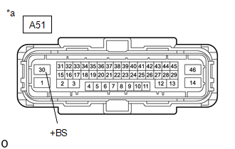
(c) Disconnect the A51 skid control ECU (brake actuator assembly) connector.
(d) Check both the connector case and the terminals for deformation and corrosion.
OK:
No deformation or corrosion.
(e) Measure the resistance according to the value(s) in the table below.
Standard Resistance:
|
Tester Connection |
Condition |
Specified Condition |
|---|---|---|
|
2 (ABS NO. 2 fuse holder) - A51-30 (+BS) |
Ignition switch off |
Below 1 Ω |
|
2 (ABS NO. 2 fuse holder) and A51-30 (+BS) - Body ground |
Ignition switch off |
10 kΩ or higher |
| NG |
|
REPAIR OR REPLACE HARNESS OR CONNECTOR |
|
|
3. |
CHECK HARNESS AND CONNECTOR (+BS TERMINAL) |
|
(a) Make sure that there is no looseness at the locking part and the connecting part of the connector. OK: The connector is securely connected. |
|
(b) Disconnect the A51 skid control ECU (brake actuator assembly) connector.
(c) Check both the connector case and the terminals for deformation and corrosion.
OK:
No deformation or corrosion.
(d) Measure the voltage according to the value(s) in the table below.
Standard Voltage:
|
Tester Connection |
Condition |
Specified Condition |
|---|---|---|
|
A51-30 (+BS) - Body ground |
Ignition switch off |
11 to 14 V |
| NG |
|
REPAIR OR REPLACE HARNESS OR CONNECTOR |
|
|
4. |
CHECK HARNESS AND CONNECTOR (GND1 TERMINAL) |
(a) Make sure that there is no looseness at the locking part and the connecting part of the connector.
OK:
The connector is securely connected.
(b) Disconnect the A51 skid control ECU (brake actuator assembly) connector.
(c) Check both the connector case and the terminals for deformation and corrosion.
OK:
No deformation or corrosion.
(d) Measure the resistance according to the value(s) in the table below.
Standard Resistance:
|
Tester Connection |
Condition |
Specified Condition |
|---|---|---|
|
A51-46 (GND1) - Body ground |
1 minute or more after disconnecting the cable from the negative (-) battery terminal |
Below 1 Ω |
| NG |
|
REPAIR OR REPLACE HARNESS OR CONNECTOR |
|
|
5. |
CLEAR DTC |
(a) Clear the DTCs.
Chassis > Brake > Clear DTCs
(b) Turn the ignition switch off.
|
|
6. |
RECONFIRM DTC |
(a) Based on the Freeze Frame Data and interview with the customer, attempt to reproduce the conditions when the malfunction occurred.
(b) Check if the same DTC is output.
Chassis > Brake > Trouble Codes
|
Result |
Proceed to |
|---|---|
|
C117A49 is not output |
A |
|
C117A49 is output |
B |
| A |
|
| B |
|
REPLACE BRAKE ACTUATOR ASSEMBLY
|
|
|
|