| Last Modified: 08-22-2025 | 6.11:8.1.0 | Doc ID: RM0000003TPCPNV |
| Model Year Start: 2024 | Model: GR Corolla | Prod Date Range: [08/2023 - ] |
| Title: BRAKE CONTROL / DYNAMIC CONTROL SYSTEMS: ELECTRONICALLY CONTROLLED BRAKE SYSTEM (for Gasoline Model with Electric Parking Brake System): C116516; ABS Pump Motor Drive Circuit Supply Voltage Circuit Voltage Below Threshold; 2024 - 2026 MY Corolla Corolla Hatchback GR Corolla [08/2023 - ] | ||
|
DTC |
C116516 |
ABS Pump Motor Drive Circuit Supply Voltage Circuit Voltage Below Threshold |
DESCRIPTION
The ABS motor relay is built into the brake actuator assembly.
When the skid control ECU (brake actuator assembly) operates ABS, TRAC, VSC, brake hold or brake assist, the ABS motor relay turns ON and drives the motor pump built into the brake actuator assembly.
If the voltage supplied to the motor relay (+BM terminal) is below the DTC detection threshold due to low voltage from the battery or DC/DC converter circuit, these DTCs may be stored.
|
DTC No. |
Detection Item |
DTC Detection Condition |
Trouble Area |
MIL |
Note |
|---|---|---|---|---|---|
|
C116516 |
ABS Pump Motor Drive Circuit Supply Voltage Circuit Voltage Below Threshold |
After driving at a speed of 6 km/h (4 mph) or more, a low voltage condition is detected in the ABS motor drive circuit. |
Skid control ECU (brake actuator assembly) |
Does not come on |
- |
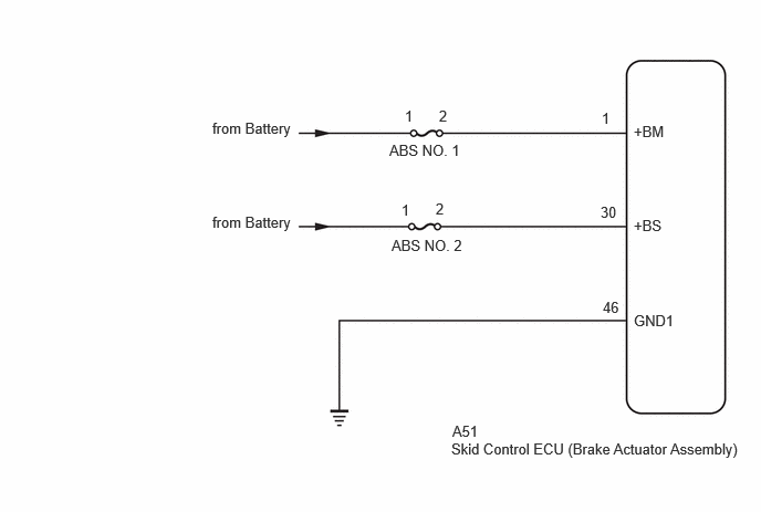
WIRING DIAGRAM
CAUTION / NOTICE / HINT
NOTICE:
- Inspect the fuses for circuits related to this system before performing the following procedure.
-
Before performing troubleshooting, make sure to confirm that the battery voltage is normal.
Click here
![2019 - 2026 MY Corolla Corolla Hatchback Corolla HV GR Corolla [06/2018 - ]; INTRODUCTION: HOW TO TROUBLESHOOT ECU CONTROLLED SYSTEMS: HOW TO PROCEED WITH TROUBLESHOOTING](/t3Portal/stylegraphics/info.gif)
PROCEDURE
|
1. |
CHECK FREEZE FRAME DATA (+BS VOLTAGE AND +BM VOLTAGE) |
(a) Select a DTC to display the Freeze Frame Data.
(b) Read the freeze frame data of DTC C116516.
Chassis > Brake
|
Tester Display |
Measurement Item |
Range |
Normal Condition |
Diagnostic Note |
|---|---|---|---|---|
|
+BS Voltage |
+BS voltage value (value detected by ECU) |
Min.: 0.0 V, Max.: 25.5 V |
Ignition switch ON: 11.0 to 14.0 V |
Changes in proportion to battery voltage HINT: This is the voltage detected at terminal +BS (which supplies power to each solenoid) of the skid control ECU (brake actuator assembly) |
|
+BM Voltage |
+BM voltage value (value detected by ECU) |
Min.: 0.0 V, Max.: 25.5 V |
Ignition switch ON: 11.0 to 14.0 V |
Changes in proportion to battery voltage HINT: This is the voltage detected at terminal +BM (which supplies power to the ABS motor) of the skid control ECU (brake actuator assembly) |
Chassis > Brake > DTC(C116516) > Freeze Frame Data
|
Tester Display |
|---|
|
+BS Voltage |
|
+BM Voltage |
|
Result |
Proceed to |
|---|---|
|
+BS Voltage and +BM Voltage are less than 9.6 V. |
A |
|
+BS Voltage is less than 9.6 V, and +BM voltage is 9.6 V or more. |
B |
|
+BS Voltage is 9.6 V or more. |
C |
| A |

|
CHECK OR REPLACE CHARGING SYSTEM COMPONENT OR BATTERY
|
| C |
|
REPLACE BRAKE ACTUATOR ASSEMBLY
|
|

|
2. |
CHECK VEHICLE CONDITION (CHECK FOR AFTERMARKET PARTS) |
(a) Consult with the customer to determine whether any aftermarket electrical components are currently installed to the vehicle, or had ever been installed to the vehicle in the past.
|
Result |
Proceed to |
|---|---|
|
No aftermarket electrical components. |
A |
|
Aftermarket electrical components are/were installed. |
B |
| B |
|
EFFECT OF AFTERMARKET PARTS |
|
|
3. |
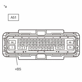
CHECK HARNESS AND CONNECTOR (ABS NO. 2 FUSE - +BS TERMINAL) |
(a) Remove the ABS No. 2 fuse from the No. 1 engine room relay block and No. 1 junction block assembly.
(b) Make sure that there is no looseness at the locking part and the connecting part of the connector.
OK:
The connector is securely connected.
(c) Disconnect the A51 skid control ECU (brake actuator assembly) connector.
(d) Check both the connector case and the terminals for deformation and corrosion.
OK:
No deformation or corrosion.
(e) Measure the resistance according to the value(s) in the table below.
Standard Resistance:
|
Tester Connection |
Condition |
Specified Condition |
|---|---|---|
|
2 (ABS NO. 2 fuse holder) - A51-30 (+BS) |
Ignition switch off |
Below 1 Ω |
|
2 (ABS NO. 2 fuse holder) and A51-30 (+BS) - Body ground |
Ignition switch off |
10 kΩ or higher |
| NG |
|
REPAIR OR REPLACE HARNESS OR CONNECTOR |
|
|
4. |
CHECK HARNESS AND CONNECTOR (+BS TERMINAL) |
|
(a) Make sure that there is no looseness at the locking part and the connecting part of the connector. OK: The connector is securely connected. |
|
(b) Disconnect the A51 skid control ECU (brake actuator assembly) connector.
(c) Check both the connector case and the terminals for deformation and corrosion.
OK:
No deformation or corrosion.
(d) Measure the voltage according to the value(s) in the table below.
Standard Voltage:
|
Tester Connection |
Condition |
Specified Condition |
|---|---|---|
|
A51-30 (+BS) - Body ground |
Ignition switch off |
9.6 V or higher |
| NG |
|
REPAIR OR REPLACE HARNESS OR CONNECTOR |
|
|
5. |
CHECK HARNESS AND CONNECTOR (GND1 TERMINAL) |
(a) Make sure that there is no looseness at the locking part and the connecting part of the connector.
OK:
The connector is securely connected.
(b) Disconnect the A51 skid control ECU (brake actuator assembly) connector.
(c) Check both the connector case and the terminals for deformation and corrosion.
OK:
No deformation or corrosion.
(d) Measure the resistance according to the value(s) in the table below.
Standard Resistance:
|
Tester Connection |
Condition |
Specified Condition |
|---|---|---|
|
A51-46 (GND1) - Body ground |
1 minute or more after disconnecting the cable from the negative (-) battery terminal |
Below 1 Ω |
| OK |
|
| NG |
|
REPAIR OR REPLACE HARNESS OR CONNECTOR |
|
|
|