| Last Modified: 08-22-2025 | 6.11:8.1.0 | Doc ID: RM0000003TPCMLQ |
| Model Year Start: 2023 | Model: Corolla | Prod Date Range: [09/2022 - ] |
| Title: BRAKE CONTROL / DYNAMIC CONTROL SYSTEMS: ELECTRONICALLY CONTROLLED BRAKE SYSTEM (for HV Model): C12BF96; Electronic Brake Booster Motor "A" Drive Circuit Component Internal Failure; 2023 - 2026 MY Corolla Corolla HV [09/2022 - ] | ||
|
DTC |
C12BF96 |
Electronic Brake Booster Motor "A" Drive Circuit Component Internal Failure |
DESCRIPTION
Refer to DTC C12BF49.
Click here
![2023 - 2026 MY Corolla Corolla HV [09/2022 - ]; BRAKE CONTROL / DYNAMIC CONTROL SYSTEMS: ELECTRONICALLY CONTROLLED BRAKE SYSTEM (for HV Model): C12BF49,...,C12BF9E; Electronic Brake Booster Motor "A" Drive Circuit Internal Electronic Failure](/t3Portal/stylegraphics/info.gif)
|
DTC No. |
Detection Item |
DTC Detection Condition |
Trouble Area |
MIL |
DTC Output from |
Note |
|---|---|---|---|---|---|---|
|
C12BF96 |
Electronic Brake Booster Motor "A" Drive Circuit Component Internal Failure |
Motor drive circuit initial check incomplete status is detected for 0.5 seconds. |
|
Comes on |
Brake Booster |
|
MONITOR DESCRIPTION
C12BF (Case 1 and 2):
- When the electronically controlled brake system is starting and a motor drive circuit malfunction is detected, the electric brake booster (brake booster with master cylinder assembly) illuminates the MIL and stores this DTC.
C12BF (Case 3, 4 and 5):
- When the electronically controlled brake system is operating or shutting down and a motor drive circuit internal malfunction is detected, the electric brake booster (brake booster with master cylinder assembly) illuminates the MIL and stores this DTC.
C12BF (Case 8):
- When the electronically controlled brake system is starting or DTC conditions are met, the self-diagnosis function performs a motor test. If the motor test does not complete within a certain amount of time, the electric brake booster (brake booster with master cylinder assembly) illuminates the MIL and stores this DTC.
MONITOR STRATEGY
|
Related DTCs |
C12BF (Case 1): Motor drive circuit start up test C12BF (Case 2): Motor drive circuit unsupported configuration monitor C12BF (Case 3): Motor drive circuit internal failure monitor C12BF (Case 4): Motor drive circuit FET monitor C12BF (Case 5): Motor drive circuit unavailable C12BF (Case 8): Motor drive circuit initial test timeout monitor |
|
Required Sensors/Components(Main) |
Electric brake booster (brake booster with master cylinder assembly) |
|
Required Sensors/Components(Related) |
Electric brake booster (brake booster with master cylinder assembly) |
|
Frequency of Operation |
During initial checking |
|
Duration |
-: C12BF (Case 1, 3, 4) 0.01 seconds: C12BF (Case 2) 0.1 seconds: C12BF (Case 5) 0.505 seconds: C12BF (Case 8) |
|
MIL Operation |
Immediately |
|
Sequence of Operation |
None |
TYPICAL ENABLING CONDITIONS
|
Monitor runs whenever the following DTCs are not stored |
TMC's intellectual property |
|
Other conditions belong to TMC's intellectual property |
- |
TYPICAL MALFUNCTION THRESHOLDS
|
TMC's intellectual property |
- |
COMPONENT OPERATING RANGE
|
TMC's intellectual property |
- |
CONFIRMATION DRIVING PATTERN
NOTICE:
When performing the normal judgment procedure, make sure that the driver door is closed and is not opened at any time during the procedure.
HINT:
- After repair has been completed, clear the DTC and then check that the vehicle has returned to normal by performing the following All Readiness check procedure.
- When clearing the permanent DTCs, refer to the "CLEAR PERMANENT DTC" procedure.
- Connect the GTS to the DLC3.
- Turn the ignition switch to ON and turn the GTS on.
- Clear the DTCs (even if no DTCs are stored, perform the clear DTC procedure).
- Turn the ignition switch off.
- Turn the ignition switch to ON (READY) and turn the GTS on.
- Depress the brake pedal several times to operate the motor of the brake booster with master cylinder assembly.[*1]
-
Wait for 1 second or more. [*2]
HINT:
[*1] to [*2]: Normal judgment procedure.
The normal judgment procedure is used to complete DTC judgment and also used when clearing permanent DTCs.
- Enter the following menus: Chassis / Brake Booster / Utility / All Readiness.
-
Check the DTC judgment result.
HINT:
- If the judgment result shows NORMAL, the system is normal.
- If the judgment result shows ABNORMAL, the system has a malfunction.
- If the judgment result shows INCOMPLETE, perform driving pattern again.
WIRING DIAGRAM
Refer to DTC C121F04.
Click here
CAUTION / NOTICE / HINT
NOTICE:
- Inspect the fuses for circuits related to this system before performing the following procedure.
-
Before performing troubleshooting, make sure to confirm that the auxiliary battery voltage is normal.
Click here
- When a decrease in auxiliary battery voltage causes a low voltage abnormality (less than 6.0 V) to occur in the electric brake booster (brake booster with master cylinder assembly), the initial check cannot start and DTC C12BF96 is stored.
PROCEDURE
|
1. |
CHECK DTC |
(a) Check the DTCs that are output.
Chassis > Brake Booster > Trouble Codes
|
Result |
Proceed to |
|---|---|
|
DTCs U012987 and U117087 are not output. |
A |
|
DTCs U012987 and U117087 are output. |
B |
| B |

|
|

|
2. |
CHECK VEHICLE CONTROL HISTORY (RoB) |
(a) Using the GTS, check for Vehicle Control History (RoB).
Chassis > Brake Booster > Utility
|
Tester Display |
|---|
|
Vehicle Control History (RoB) |
|
Result |
Proceed to |
|---|---|
|
X2152 is not stored. |
A |
|
X2152 is stored. |
B |
| B |
|
CHECK OR REPLACE CHARGING SYSTEM COMPONENT OR AUXILIARY BATTERY |
|
|
3. |
CHECK HARNESS AND CONNECTOR (+BS TERMINAL) |
|
(a) Make sure that there is no looseness at the locking part and the connecting part of the connectors. OK: The connector is securely connected. |
|
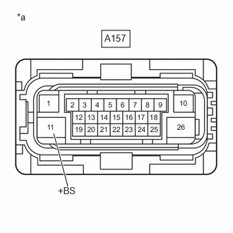
(b) Disconnect the A157 electric brake booster (brake booster with master cylinder assembly) connector.
(c) Check both the connector case and the terminals for deformation and corrosion.
OK:
No deformation or corrosion.
(d) Measure the voltage according to the value(s) in the table below.
Standard Voltage:
|
Tester Connection |
Condition |
Specified Condition |
|---|---|---|
|
A157-11 (+BS) - Body ground |
Ignition switch off |
11 to 14 V |
| NG |
|
REPAIR OR REPLACE HARNESS OR CONNECTOR |
|
|
4. |
CLEAR DTC |
(a) Clear the DTCs.
Chassis > Brake Booster > Clear DTCs
(b) Turn the ignition switch off.
|
|
5. |
RECONFIRM DTC |
(a) Based on the Freeze Frame Data and interview with the customer, attempt to reproduce the conditions when the malfunction occurred.
(b) Check if the same DTC is output.
Chassis > Brake Booster > Trouble Codes
|
Result |
Proceed to |
|---|---|
|
DTC C12BF96 is not output. |
A |
|
DTC C12BF96 is output. |
B |
| A |
|
| B |
|
|
|
|