| Last Modified: 08-22-2025 | 6.11:8.1.0 | Doc ID: RM0000003TPCMKB |
| Model Year Start: 2023 | Model: Corolla | Prod Date Range: [09/2022 - ] |
| Title: BRAKE CONTROL / DYNAMIC CONTROL SYSTEMS: ELECTRONICALLY CONTROLLED BRAKE SYSTEM (for HV Model): C052F14; ABS Pump Motor Supply Voltage Circuit Short to Ground or Open; 2023 - 2026 MY Corolla Corolla HV [09/2022 - ] | ||
|
DTC |
C052F14 |
ABS Pump Motor Supply Voltage Circuit Short to Ground or Open |
DESCRIPTION
Refer to DTC C052C11.
Click here
![2023 - 2026 MY Corolla Corolla HV [09/2022 - ]; BRAKE CONTROL / DYNAMIC CONTROL SYSTEMS: ELECTRONICALLY CONTROLLED BRAKE SYSTEM (for HV Model): C052C11,C052C13,C142719; ABS Pump Motor Control Circuit Short to Ground](/t3Portal/stylegraphics/info.gif)
|
DTC No. |
Detection Item |
DTC Detection Condition |
Trouble Area |
MIL |
DTC Output from |
Note |
|---|---|---|---|---|---|---|
|
C052F14 |
ABS Pump Motor Supply Voltage Circuit Short to Ground or Open |
Either of the following conditions are met:
|
|
Comes on |
Brake/EPB |
|
MONITOR DESCRIPTION
C055B (Case 1, 2, 4 and 5):
- The skid control ECU (brake actuator assembly) monitors the voltage of the ABS motor relay. If the voltage applied to the relay is a certain value or more or a certain value or less for a certain amount of time, the skid control ECU (brake actuator assembly) illuminates the MIL and stores this DTC.
C055B (Case 3):
- The skid control ECU (brake actuator assembly) has a self-diagnosis function that monitors the pump motor circuit. Under certain conditions, if the pump motor or motor relay self-diagnosis fails a certain number of times for a certain amount of time, the skid control ECU (brake actuator assembly) illuminates the MIL and stores this DTC.
MONITOR STRATEGY
|
Related DTCs |
C055B (Case 1): Pump motor run monitoring C055B (Case 2): Motor relay drain supply monitoring C055B (Case 3): Pump motor test timeout monitoring C055B (Case 4): Motor relay supply voltage line monitoring (out of range high) C055B (Case 5): Motor relay supply voltage line monitoring (out of range low) |
|
Required Sensors/Components(Main) |
Skid control ECU (brake actuator assembly) |
|
Required Sensors/Components(Related) |
Skid control ECU (brake actuator assembly) Speed sensor |
|
Frequency of Operation |
During initial checking |
|
Duration |
0.10 seconds: C055B (Case 4 and 5) 0.15 seconds: C055B (Case 2) 0.48 seconds: C055B (Case 1) 60 seconds: C055B (Case 3) |
|
MIL Operation |
Immediately |
|
Sequence of Operation |
None |
TYPICAL ENABLING CONDITIONS
|
Monitor runs whenever the following DTCs are not stored |
TMC's intellectual property |
|
Other conditions belong to TMC's intellectual property |
- |
TYPICAL MALFUNCTION THRESHOLDS
|
TMC's intellectual property |
- |
COMPONENT OPERATING RANGE
|
TMC's intellectual property |
- |
CONFIRMATION DRIVING PATTERN
NOTICE:
When performing the normal judgment procedure, make sure that the driver door is closed and is not opened at any time during the procedure.
HINT:
- After repair has been completed, clear the DTC and then check that the vehicle has returned to normal by performing the following All Readiness check procedure.
- When clearing the permanent DTCs, refer to the "CLEAR PERMANENT DTC" procedure.
- Connect the GTS to the DLC3.
- Turn the ignition switch to ON and turn the GTS on.
- Clear the DTCs (even if no DTCs are stored, perform the clear DTC procedure).
- Turn the ignition switch off.
- Turn the ignition switch to ON (READY) and turn the GTS on.
- Depress the brake pedal several times to operate the pump motor of the brake actuator assembly. [*1]
-
After the pump motor stops, wait for 2 seconds or more. [*2]
HINT:
[*1] to [*2]: Normal judgment procedure.
The normal judgment procedure is used to complete DTC judgment and also used when clearing permanent DTCs.
-
Enter the following menus: Chassis / Brake/EPB* / Utility / All Readiness.
*: Electric Parking Brake System
-
Check the DTC judgment result.
HINT:
- If the judgment result shows NORMAL, the system is normal.
- If the judgment result shows ABNORMAL, the system has a malfunction.
- If the judgment result shows INCOMPLETE, perform driving pattern again.
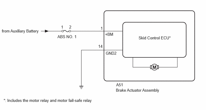
WIRING DIAGRAM
CAUTION / NOTICE / HINT
NOTICE:
- Inspect the fuses for circuits related to this system before performing the following procedure.
-
Before performing troubleshooting, make sure to confirm that the auxiliary battery voltage is normal.
Click here
PROCEDURE
|
1. |
CHECK FREEZE FRAME DATA (+BM VOLTAGE) |
(a) Select a DTC to display the Freeze Frame Data.
(b) Read the freeze frame data of DTC C052F14.
Chassis > Brake/EPB
|
Tester Display |
Measurement Item |
Range |
Normal Condition |
Diagnostic Note |
|---|---|---|---|---|
|
+BM Voltage |
+BM voltage value (value detected by ECU) |
Min.: 0.0 V, Max.: 25.5 V |
Ignition switch ON: 11.0 to 14.0 V |
Changes in proportion to auxiliary battery voltage HINT: This is the voltage detected at terminal +BM (which supplies power to the ABS motor) of the skid control ECU (brake actuator assembly) |
Chassis > Brake/EPB > DTC(C052F14) > Freeze Frame Data
|
Tester Display |
|---|
|
+BM Voltage |
|
Result |
Proceed to |
|---|---|
|
The value of +BM Voltage is less than 1.5 V. |
A |
|
The value of +BM Voltage is 1.5 V or more. |
B |
| B |

|
|

|
2. |
CHECK VEHICLE CONDITION (CHECK FOR AFTERMARKET PARTS) |
(a) Consult with the customer to determine whether any aftermarket electrical components are currently installed to the vehicle, or had ever been installed to the vehicle in the past.
|
Result |
Proceed to |
|---|---|
|
No aftermarket electrical components. |
A |
|
Aftermarket electrical components are/were installed. |
B |
| B |
|
EFFECT OF AFTERMARKET PARTS |
|
|
3. |
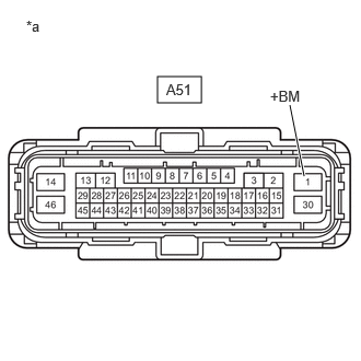
CHECK HARNESS AND CONNECTOR (ABS NO. 1 FUSE - +BM TERMINAL) |
(a) Remove the ABS No. 1 fuse from the No. 1 engine room relay block and No. 1 junction block assembly.
(b) Make sure that there is no looseness at the locking part and the connecting part of the connector.
OK:
The connector is securely connected.
(c) Disconnect the A51 skid control ECU (brake actuator assembly) connector.
(d) Check both the connector case and the terminals for deformation and corrosion.
OK:
No deformation or corrosion.
(e) Measure the resistance according to the value(s) in the table below.
Standard Resistance:
|
Tester Connection |
Condition |
Specified Condition |
|---|---|---|
|
2 (ABS NO. 1 fuse holder) - A51-1 (+BM) |
Ignition switch off |
Below 1 Ω |
|
2 (ABS NO. 1 fuse holder) and A51-1 (+BM) - Body ground |
Ignition switch off |
10 kΩ or higher |
| NG |
|
REPAIR OR REPLACE HARNESS OR CONNECTOR |
|
|
4. |
CHECK HARNESS AND CONNECTOR (+BM TERMINAL) |
|
(a) Make sure that there is no looseness at the locking part and the connecting part of the connector. OK: The connector is securely connected. |
|
(b) Disconnect the A51 skid control ECU (brake actuator assembly) connector.
(c) Check both the connector case and the terminals for deformation and corrosion.
OK:
No deformation or corrosion.
(d) Measure the voltage according to the value(s) in the table below.
Standard Voltage:
|
Tester Connection |
Condition |
Specified Condition |
|---|---|---|
|
A51-1 (+BM) - Body ground |
Ignition switch off |
11 to 14 V |
| NG |
|
REPAIR OR REPLACE HARNESS OR CONNECTOR |
|
|
5. |
CHECK HARNESS AND CONNECTOR (GND2 TERMINAL) |
(a) Make sure that there is no looseness at the locking part and the connecting part of the connector.
OK:
The connector is securely connected.
(b) Disconnect the A51 skid control ECU (brake actuator assembly) connector.
(c) Check both the connector case and the terminals for deformation and corrosion.
OK:
No deformation or corrosion.
(d) Measure the resistance according to the value(s) in the table below.
Standard Resistance:
|
Tester Connection |
Condition |
Specified Condition |
|---|---|---|
|
A51-14 (GND2) - Body ground |
1 minute or more after disconnecting the cable from the negative (-) auxiliary battery terminal |
Below 1 Ω |
| NG |
|
REPAIR OR REPLACE HARNESS OR CONNECTOR |
|
|
6. |
CLEAR DTC |
(a) Clear the DTCs.
Chassis > Brake/EPB > Clear DTCs
(b) Turn the ignition switch off.
|
|
7. |
RECONFIRM DTC |
(a) Based on the Freeze Frame Data and interview with the customer, attempt to reproduce the conditions when the malfunction occurred.
(b) Check if the same DTC is output.
Chassis > Brake/EPB > Trouble Codes
|
Result |
Proceed to |
|---|---|
|
C052F14 is not output. |
A |
|
C052F14 is output. |
B |
| A |
|
| B |
|
REPLACE BRAKE ACTUATOR ASSEMBLY
|
|
8. |
CHECK FREEZE FRAME DATA (+BM VOLTAGE) |
(a) Select a DTC to display the Freeze Frame Data.
(b) Read the freeze frame data of DTC C052F14.
Chassis > Brake/EPB
|
Tester Display |
Measurement Item |
Range |
Normal Condition |
Diagnostic Note |
|---|---|---|---|---|
|
+BM Voltage |
+BM voltage value (value detected by ECU) |
Min.: 0.0 V, Max.: 25.5 V |
Ignition switch ON: 11.0 to 14.0 V |
Changes in proportion to auxiliary battery voltage HINT: This is the voltage detected at terminal +BM (which supplies power to the ABS motor) of the skid control ECU (brake actuator assembly) |
Chassis > Brake/EPB > DTC(C052F14) > Freeze Frame Data
|
Tester Display |
|---|
|
+BM Voltage |
HINT:
If the +BM terminal voltage is higher than 25.5 V, the display will still show 25.5 V.
|
Result |
Proceed to |
|---|---|
|
The value of +BM Voltage is 25.5 V or more. |
A |
|
The value of +BM Voltage is less than 25.5 V. |
B |
| B |
|
REPLACE BRAKE ACTUATOR ASSEMBLY
|
|
|
9. |
CHECK FREEZE FRAME DATA (+BS VOLTAGE) |
(a) Select a DTC to display the Freeze Frame Data.
(b) Read the freeze frame data of DTC C052F14.
Chassis > Brake/EPB
|
Tester Display |
Measurement Item |
Range |
Normal Condition |
Diagnostic Note |
|---|---|---|---|---|
|
+BS Voltage |
+BS voltage value (value detected by ECU) |
Min.: 0.0 V, Max.: 25.5 V |
Ignition switch ON: 11.0 to 14.0 V |
Changes in proportion to auxiliary battery voltage HINT: This is the voltage detected at terminal +BS (which supplies power to each solenoid) of the skid control ECU (brake actuator assembly) |
Chassis > Brake/EPB > DTC(C052F14) > Freeze Frame Data
|
Tester Display |
|---|
|
+BS Voltage |
HINT:
If the +BS terminal voltage is higher than 25.5 V, the display will still show 25.5 V.
|
Result |
Proceed to |
|---|---|
|
The value of +BS Voltage is less than 25.5 V. |
A |
|
The value of +BS Voltage is 25.5 V or more. |
B |
| B |
|
CHECK OR REPLACE CHARGING SYSTEM COMPONENT OR AUXILIARY BATTERY |
|
|
10. |
CHECK VEHICLE CONDITION (CHECK FOR AFTERMARKET PARTS) |
(a) Consult with the customer to determine whether any aftermarket electrical components are currently installed to the vehicle, or had ever been installed to the vehicle in the past.
|
Result |
Proceed to |
|---|---|
|
No aftermarket electrical components. |
A |
|
Aftermarket electrical components are/were installed. |
B |
| B |
|
EFFECT OF AFTERMARKET PARTS |
|
|
11. |
CHECK HARNESS AND CONNECTOR (ABS NO. 1 FUSE - +BM TERMINAL) |
(a) Remove the ABS No. 1 fuse from the No. 1 engine room relay block and No. 1 junction block assembly.
(b) Make sure that there is no looseness at the locking part and the connecting part of the connector.
OK:
The connector is securely connected.
(c) Disconnect the A51 skid control ECU (brake actuator assembly) connector.
(d) Check both the connector case and the terminals for deformation and corrosion.
OK:
No deformation or corrosion.
(e) Measure the resistance according to the value(s) in the table below.
Standard Resistance:
|
Tester Connection |
Condition |
Specified Condition |
|---|---|---|
|
2 (ABS NO. 1 fuse holder) - A51-1 (+BM) |
Ignition switch off |
Below 1 Ω |
| NG |
|
REPAIR OR REPLACE HARNESS OR CONNECTOR |
|
|
12. |
CLEAR DTC |
(a) Clear the DTCs.
Chassis > Brake/EPB > Clear DTCs
(b) Turn the ignition switch off.
|
|
13. |
RECONFIRM DTC |
(a) Based on the Freeze Frame Data and interview with the customer, attempt to reproduce the conditions when the malfunction occurred.
(b) Check if the same DTC is output.
Chassis > Brake/EPB > Trouble Codes
|
Result |
Proceed to |
|---|---|
|
C052F14 is not output. |
A |
|
C052F14 is output. |
B |
| A |
|
| B |
|
REPLACE BRAKE ACTUATOR ASSEMBLY
|
|
|
|