| Last Modified: 08-22-2025 | 6.11:8.1.0 | Doc ID: RM0000003TPCFWD |
| Model Year Start: 2026 | Model: GR Corolla | Prod Date Range: [08/2025 - ] |
| Title: UC80F (AUTOMATIC TRANSMISSION / TRANSAXLE): PARK / NEUTRAL POSITION SWITCH: INSTALLATION; 2026 MY Corolla Corolla Hatchback GR Corolla [08/2025 - ] | ||
INSTALLATION
PROCEDURE
1. INSTALL PARK/NEUTRAL POSITION SWITCH ASSEMBLY
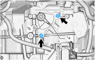
(a) Temporarily install the park/neutral position switch assembly to the automatic transaxle case sub-assembly with the 2 bolts.
NOTICE:
Before installing the park/neutral position switch assembly, remove any dirt or rust on the manual valve lever shaft sub-assembly. Be sure to install the park/neutral position switch assembly straight along the manual valve lever shaft sub-assembly while being careful not to deform the plate spring that supports the manual valve lever shaft sub-assembly. If the plate spring is deformed, the park/neutral position switch assembly cannot be installed correctly.
(b) Temporarily install the transmission control shaft lever to the manual valve lever shaft sub-assembly.
|
(c) Turn the transmission control shaft lever clockwise until it stops, then turn it counterclockwise 2 notches. |
|
(d) Remove the transmission control shaft lever from the manual valve lever shaft sub-assembly.
|
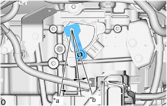
(e) Align the protrusion with the neutral basic line. |
|
(f) Hold the park/neutral position switch assembly in that position and tighten the 2 bolts.
Torque:
5.4 N·m {55 kgf·cm, 48 in·lbf}
(g) Install the transmission control shaft lever to the manual valve lever shaft sub-assembly with the washer and nut.
Torque:
12.7 N·m {130 kgf·cm, 9 ft·lbf}
(h) Connect the park/neutral position switch assembly connector.
2. CONNECT TRANSMISSION CONTROL CABLE ASSEMBLY
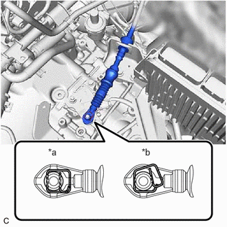
(a) Connect the transmission control cable assembly to the No. 1 transmission control cable bracket with a new clip.
|
(b) Connect the transmission control cable assembly to the transmission control shaft lever as shown in the illustration. NOTICE: Before connecting the transmission control cable assembly, check that the park/neutral position switch assembly and shift lever are in N. |
|
3. CONNECT WIRE HARNESS
(a) Engage the 2 clamps to connect the wire harness.
(b) Install the bolt.
Torque:
10 N·m {102 kgf·cm, 7 ft·lbf}
(c) Connect the engine coolant temperature sensor connector.
|
(d) Connect the 3 ECM connectors and rotate the 3 levers to lock them. NOTICE:
|
|
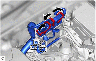
(e) Engage the 4 clamps.
4. CONNECT FUEL VAPOR FEED HOSE
(a) Engage the clamp to connect the fuel vapor feed hose.
5. INSTALL AIR CLEANER WITH AIR CLEANER HOSE
Click here
![2026 MY GR Corolla [08/2025 - ]; G16E-GTS (EMISSION CONTROL): MONOLITHIC CONVERTER: INSTALLATION+](/t3Portal/stylegraphics/info.gif)
6. INSTALL INLET NO. 1 AIR CLEANER
7. INSTALL RADIATOR SUPPORT OPENING COVER
Click here
8. INSTALL NO. 4 INLET AIR CLEANER
Click here
9. CONNECT CABLE TO NEGATIVE BATTERY TERMINAL
Click here
10. INSTALL DECK BOARD ASSEMBLY
Click here
11. INITIALIZATION AFTER RECONNECTING BATTERY TERMINAL
HINT:
When disconnecting and reconnecting the battery, there is an automatic learning function that completes learning when the respective system is used.
Click here
12. INSPECT PARK/NEUTRAL POSITION SWITCH ASSEMBLY OPERATION
Click here
13. INSPECT SHIFT LEVER POSITION
Click here
14. ADJUST SHIFT LEVER POSITION
Click here
|
|
|