| Last Modified: 01-30-2024 | 6.11:8.1.0 | Doc ID: RM100000002GAKR |
| Model Year Start: 2024 | Model: RAV4 | Prod Date Range: [10/2023 - ] |
| Title: BRAKE CONTROL / DYNAMIC CONTROL SYSTEMS: ELECTRONICALLY CONTROLLED BRAKE SYSTEM (w/o Vacuum Brake Booster): C11001C; Brake Pedal Position Sensor "A" Supply Voltage Circuit Voltage Out of Range; 2024 MY RAV4 RAV4 HV [10/2023 - ] | ||
|
DTC |
C11001C |
Brake Pedal Position Sensor "A" Supply Voltage Circuit Voltage Out of Range |
DESCRIPTION
Refer to DTC C110000.
Click here
![2024 MY RAV4 RAV4 HV [10/2023 - ]; BRAKE CONTROL / DYNAMIC CONTROL SYSTEMS: ELECTRONICALLY CONTROLLED BRAKE SYSTEM (w/o Vacuum Brake Booster): C110000; Brake Pedal Position Sensor "A" Supply Voltage Malfunction](/t3Portal/stylegraphics/info.gif)
|
DTC No. |
Detection Item |
DTC Detection Condition |
Trouble Area |
MIL |
Note |
|---|---|---|---|---|---|
|
C11001C |
Brake Pedal Position Sensor "A" Supply Voltage Circuit Voltage Out of Range |
The sensor supply voltage (VCSK) is 4.7 V or less, or 5.3 V or more for 0.2 seconds or more. |
|
Comes on |
|
C11001C DTC Detection Conditions
|
Vehicle Condition |
|||
|---|---|---|---|
|
Pattern 1 |
Pattern 2 |
||
|
Diagnosis Condition |
- |
- |
- |
|
Malfunction Status |
The sensor supply voltage (VCSK) is 4.7 V or less |
○ |
- |
|
The sensor supply voltage (VCSK) is 5.3 V or more |
- |
○ |
|
|
Detection Time |
0.2 seconds or more. |
0.2 seconds or more. |
|
|
Number of Trips |
1 trip |
1 trip |
|
HINT:
DTC will be output when conditions for either of the patterns in the table above are met.
MONITOR DESCRIPTION
The No. 2 skid control ECU (brake actuator assembly) monitors the power supply voltage of the brake pedal stroke sensor assembly. When the brake pedal stroke sensor assembly power supply voltage is outside of the normal range, the No. 2 skid control ECU (brake actuator assembly) judges that the power supply is abnormal and illuminates the MIL and stores this DTC.
MONITOR STRATEGY
|
Related DTCs |
C1100 (Case 1): Brake pedal position sensor voltage circuit/open |
|
Required Sensors/Components(Main) |
No. 2 skid control ECU (brake actuator assembly) |
|
Required Sensors/Components(Related) |
No. 2 skid control ECU (brake actuator assembly) |
|
Frequency of Operation |
Continuous |
|
Duration |
0.198 seconds |
|
MIL Operation |
Immediately |
|
Sequence of Operation |
None |
TYPICAL ENABLING CONDITIONS
|
Monitor runs whenever the following DTCs are not stored |
C14C7 (Case 3 to 9): Brake system voltage circuit low |
|
Brake system voltage |
Higher than 7.3 V |
TYPICAL MALFUNCTION THRESHOLDS
|
Brake pedal position sensor power supply |
Less than 4.8 V, or higher than 5.2 V |
COMPONENT OPERATING RANGE
|
Both of the following conditions are met |
- |
|
Brake system voltage |
Higher than 7.3 V |
|
Brake pedal position sensor power supply |
4.8 V or more, and 5.2 V or less |
CONFIRMATION DRIVING PATTERN
NOTICE:
When performing the normal judgment procedure, make sure that the driver door is closed and is not opened at any time during the procedure.
HINT:
- After repair has been completed, clear the DTC and then check that the vehicle has returned to normal by performing the following All Readiness check procedure.
- When clearing the permanent DTCs, refer to the "CLEAR PERMANENT DTC" procedure.
- Connect the GTS to the DLC3.
- Turn the ignition switch to ON and turn the GTS on.
- Clear the DTCs (even if no DTCs are stored, perform the clear DTC procedure).
- Turn the ignition switch off.
- Turn the ignition switch to ON (READY) and turn the GTS on.
-
Wait for 1 second or more. [*]
HINT:
[*]: Normal judgment procedure.
The normal judgment procedure is used to complete DTC judgment and also used when clearing permanent DTCs.
- Enter the following menus: Chassis / Brake/EPB / Utility / All Readiness.
-
Check the DTC judgment result.
HINT:
- If the judgment result shows NORMAL, the system is normal.
- If the judgment result shows ABNORMAL, the system has a malfunction.
- If the judgment result shows INCOMPLETE, perform driving pattern again.
WIRING DIAGRAM
Refer to DTC C110000.
Click here
CAUTION / NOTICE / HINT
NOTICE:
-
After replacing or reinstalling the brake pedal stroke sensor assembly, perform "Calibration" after performing "Reset Memory".
Click here
-
After replacing the No. 1 skid control ECU (brake booster with master cylinder assembly), perform "Calibration" after performing "Reset Memory".
Click here
PROCEDURE
|
1. |
CHECK BRAKE PEDAL |
(a) Check that the brake pedal and the brake pedal stroke sensor assembly are properly installed and that the pedal can be depressed normally.
(b) Check and adjust the brake pedal height.
Click here
(c) Adjust the brake pedal stroke sensor assembly.
Click here
|

|
2. |
CHECK HARNESS AND CONNECTOR (BRAKE BOOSTER WITH MASTER CYLINDER ASSEMBLY - BRAKE PEDAL STROKE SENSOR ASSEMBLY) |
(a) Turn the ignition switch off.
(b) Make sure that there is no looseness at the locking part and the connecting part of the connectors.
OK:
The connector is securely connected.
(c) Disconnect the A104 No. 1 skid control ECU (brake booster with master cylinder assembly) connector.
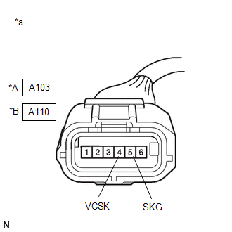
(d) Disconnect the A103*1 or A110*2 brake pedal stroke sensor assembly connector.
- *1: except TMC Made
- *2: for TMC Made
(e) Check both the connector case and the terminals for deformation and corrosion.
OK:
No deformation or corrosion.
(f) Measure the resistance according to the value(s) in the table below.
Standard Resistance:
except TMC Made
|
Tester Connection |
Condition |
Specified Condition |
|---|---|---|
|
A104-18 (SKG1) - A103-5 (SKG) |
Always |
Below 1 Ω |
|
A104-18 (SKG1) or A103-5 (SKG) - Body ground |
Always |
10 kΩ or higher |
|
A104-16 (VSK1) - A103-4 (VCSK) |
Always |
Below 1 Ω |
|
A104-16 (VSK1) or A103-4 (VCSK) - Body ground |
Always |
10 kΩ or higher |
for TMC Made
|
Tester Connection |
Condition |
Specified Condition |
|---|---|---|
|
A104-18 (SKG1) - A110-5 (SKG) |
Always |
Below 1 Ω |
|
A104-18 (SKG1) or A110-5 (SKG) - Body ground |
Always |
10 kΩ or higher |
|
A104-16 (VSK1) - A110-4 (VCSK) |
Always |
Below 1 Ω |
|
A104-16 (VSK1) or A110-4 (VCSK) - Body ground |
Always |
10 kΩ or higher |
| NG |

|
REPAIR OR REPLACE HARNESS OR CONNECTOR |
|
|
3. |
INSPECT BRAKE BOOSTER WITH MASTER CYLINDER ASSEMBLY (SENSOR OUTPUT) |
|
(a) Reconnect the A104 No. 1 skid control ECU (brake booster with master cylinder assembly) connector. |
|
(b) Turn the ignition switch to ON.
(c) Measure the voltage according to the value(s) in the table below.
Standard Voltage:
except TMC Made
|
Tester Connection |
Condition |
Specified Condition |
|---|---|---|
|
A103-4 (VCSK) - A103-5 (SKG) |
Ignition switch ON |
4.84 to 5.16 V |
for TMC Made
|
Tester Connection |
Condition |
Specified Condition |
|---|---|---|
|
A110-4 (VCSK) - A110-5 (SKG) |
Ignition switch ON |
4.84 to 5.16 V |
| OK |
|
| NG |
|
|
|
|