- Perform "Reset Memory"
- Perform "Calibration"
| Last Modified: 05-08-2025 | 6.11:8.1.0 | Doc ID: RM100000002FR7C |
| Model Year Start: 2024 | Model: RAV4 | Prod Date Range: [10/2023 - ] |
| Title: AXLE AND DIFFERENTIAL: FRONT AXLE HUB: REMOVAL; 2024 - 2025 MY RAV4 RAV4 HV [10/2023 - ] | ||
REMOVAL
CAUTION / NOTICE / HINT
The necessary procedures (adjustment, calibration, initialization, or registration) that must be performed after parts are removed and installed, or replaced during front axle hub assembly removal/installation are shown below.
Necessary Procedures After Parts Removed/Installed/Replaced (for HV Model:)
|
Replaced Part or Performed Procedure |
Necessary Procedures |
Effect/Inoperative Function When Necessary Procedures are not Performed |
Link |
|---|---|---|---|
|
*: When performing learning using the Techstream.
Click here
|
|||
|
Auxiliary battery terminal is disconnected/reconnected |
Perform steering sensor zero point calibration |
Lane control system |
|
|
Parking support brake system (for HV model)* |
|||
|
Pre-collision system |
|||
|
Reset back door close position |
Power back door system |
|
|
|
Back door lock initialization |
Power door lock control system |
|
|
|
Front wheel alignment adjustment |
|
|
|
NOTICE:
- After the ignition switch is turned off, the audio and visual system records various types of memory and settings. As a result, after turning the ignition switch off, make sure to wait at least 2 minutes before disconnecting the cable from the negative (-) auxiliary battery terminal.
- When the cable is disconnected from the negative (-) auxiliary battery terminal and the security lock setting has been enabled, multi-display operations will be disabled upon next startup unless the password is entered. Be sure to check the security lock setting before disconnecting the cable from the negative (-) auxiliary battery terminal.
Necessary Procedures After Parts Removed/Installed/Replaced (for Gasoline Model:)
|
Replaced Part or Performed Procedure |
Necessary Procedure |
Effect/Inoperative Function When Necessary Procedures are not Performed |
Link |
|---|---|---|---|
|
Front wheel alignment adjustment |
|
|
|
HINT:
- Use the same procedure for the RH and LH sides.
- The following procedure is for the LH side.
PROCEDURE
1. DISABLE BRAKE CONTROL (w/o Vacuum Brake Booster)
Click here
![2024 - 2025 MY RAV4 RAV4 HV [10/2023 - ]; BRAKE (REAR): REAR BRAKE: REMOVAL+](/t3Portal/stylegraphics/info.gif)
2. REMOVE FRONT WHEEL
Click here
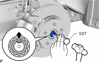
3. REMOVE FRONT AXLE SHAFT NUT LH
|
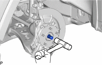
(a) Using SST and a hammer, unstake the staked part of the front axle shaft nut. SST: 09930-00010 09931-00010 09931-00020 NOTICE: Loosen the staked part of the front axle shaft nut completely, otherwise the screw of the drive shaft may be damaged. |
|
(b) While applying the brakes, remove the front axle shaft nut.
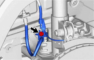
4. DISCONNECT FRONT SPEED SENSOR LH
|
(a) Remove the bolt and disconnect the front speed sensor and front flexible hose from the front shock absorber assembly. NOTICE: Be sure to separate the front speed sensor and front flexible hose from the front shock absorber assembly completely. |
|
|
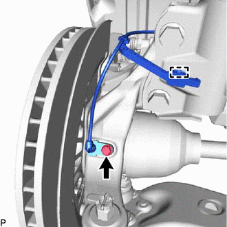
(b) Remove the bolt, disengage the clamp and disconnect the front speed sensor from the front shock absorber assembly and steering knuckle. NOTICE:
|
|
5. DISCONNECT TIE ROD ASSEMBLY LH
Click here
6. DISCONNECT FRONT DISC BRAKE CALIPER ASSEMBLY LH
Click here
7. REMOVE FRONT DISC
Click here
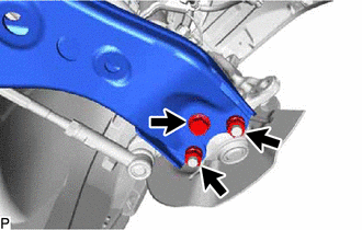
8. DISCONNECT FRONT LOWER NO. 1 SUSPENSION ARM SUB-ASSEMBLY LH
|
(a) Remove the bolt and 2 nuts and disconnect the front lower No. 1 suspension arm sub-assembly from the front lower ball joint assembly. |
|
9. DISCONNECT FRONT DRIVE SHAFT ASSEMBLY LH
|
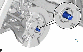
(a) Place matchmarks on the front axle hub LH and front drive shaft assembly LH as shown in the illustration. |
|
|
(b) Using a plastic hammer, disconnect the front drive shaft assembly from the front axle assembly. NOTICE:
HINT: If it is difficult to separate the front drive shaft assembly from the front axle assembly, tap the end of the front drive shaft assembly using a brass bar and a hammer. |
|
10. REMOVE FRONT AXLE ASSEMBLY LH
|
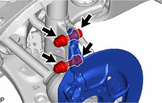
(a) Remove the 2 bolts, 2 nuts and front axle assembly from the front shock absorber assembly. NOTICE: When removing the nuts, keep the bolts from rotating. |
|
11. REMOVE FRONT AXLE HUB SUB-ASSEMBLY LH
|
(a) Secure the front axle assembly between aluminum plates in a vise. NOTICE: Do not overtighten the vise. |
|
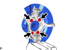
(b) Remove the 4 bolts, front axle hub sub-assembly and front disc brake dust cover from the steering knuckle.
NOTICE:
- Do not drop the front axle hub sub-assembly.
- Be careful not to damage the speed sensor rotor or contact surfaces.
- Do not allow foreign matter to contact the speed sensor rotor or contact surfaces.
|
|
|