- DTCs are stored
- Slight vibration at a vehicle speed of 5 km/h (3 mph) or less
- Shock or vibration during acceleration
| Last Modified: 01-30-2024 | 6.11:8.1.0 | Doc ID: RM100000002FR6S |
| Model Year Start: 2024 | Model: RAV4 HV | Prod Date Range: [10/2023 - ] |
| Title: HYBRID / BATTERY CONTROL: INVERTER WITH CONVERTER (for AWD): REMOVAL; 2024 MY RAV4 HV [10/2023 - ] | ||
REMOVAL
CAUTION / NOTICE / HINT
The necessary procedures (adjustment, calibration, initialization, or registration) that must be performed after parts are removed and installed, or replaced during inverter with converter assembly removal/installation are shown below.
Necessary Procedures After Parts Removed/Installed/Replaced
|
Replaced Part or Performed Procedure |
Necessary Procedures |
Effect/Inoperative Function when Necessary Procedure not Performed |
Link |
|---|---|---|---|
|
*: When performing learning using the Techstream.
Click here
|
|||
|
Auxiliary battery terminal is disconnected/reconnected |
Perform steering sensor zero point calibration |
Lane control system |
|
|
Parking support brake system* |
|||
|
Pre-collision system |
|||
|
Reset back door close position |
Power back door system |
|
|
|
Back door lock initialization |
Power door lock control system |
|
|
|
Replacement of inverter with converter assembly |
Resolver learning |
|
for NICKEL METAL HYDRIDE BATTERY:
for LITHIUM-ION BATTERY:
|
|
Replacement of ECM |
Perform Vehicle Identification Number (VIN) registration |
DTC P063051 is output |
|
|
Grill shutter switch specification infomation |
Vehicle control history (RoB) [X260E] is stored |
|
|
CAUTION:
-
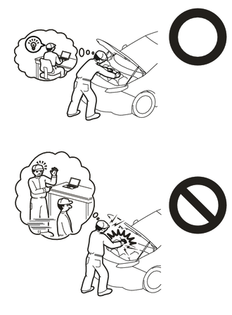
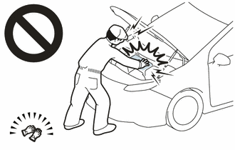
Orange wire harnesses and connectors indicate high-voltage circuits. To prevent electric shock, always follow the procedure described in the repair manual.
-
for NICKEL METAL HYDRIDE BATTERY:
Click here
![2019 - 2024 MY RAV4 HV [02/2019 - ]; HYBRID / BATTERY CONTROL: HYBRID CONTROL SYSTEM (for AWD with NICKEL METAL HYDRIDE BATTERY): PRECAUTION](/t3Portal/stylegraphics/info.gif)
-
for LITHIUM-ION BATTERY:
Click here
-
for NICKEL METAL HYDRIDE BATTERY:
-
To prevent electric shock, wear insulated gloves when working on wire harnesses and components of the high voltage system.
NOTICE:
After the ignition switch is turned off, the radio and display receiver assembly records various types of memory and settings. As a result, after turning the ignition switch off, be sure to wait for the time specified in the following table before disconnecting the cable from the negative (-) auxiliary battery terminal.
Waiting Time before Disconnecting Cable from Negative (-) Auxiliary Battery Terminal
|
System Name |
See Procedure |
|---|---|
|
Vehicle enrolled in Toyota Audio Multimedia system or safety connect system |
6 minutes |
|
Vehicle not enrolled in Toyota Audio Multimedia system and safety connect system |
1 minute |
PROCEDURE
1. PRECAUTION
NOTICE:
After turning the ignition switch off, waiting time may be required before disconnecting the cable from the negative (-) auxiliary battery terminal. Therefore, make sure to read the disconnecting the cable from the negative (-) auxiliary battery terminal notices before proceeding with work.
2. REMOVE SERVICE PLUG GRIP
Click here
3. DRAIN COOLANT (for Inverter)
Click here
4. REMOVE NO. 1 ENGINE COVER SUB-ASSEMBLY
Click here
5. REMOVE INLET AIR CLEANER ASSEMBLY
Click here
6. REMOVE AIR CLEANER ASSEMBLY WITH AIR CLEANER HOSE
Click here
7. REMOVE ECM
Click here
8. DISCONNECT ENGINE ROOM MAIN WIRE
CAUTION:
Be sure to wear insulated gloves.
NOTICE:
Do not allow any foreign matter or water to enter the inverter with converter assembly.
|
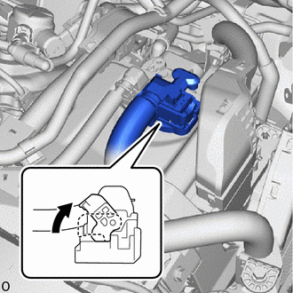
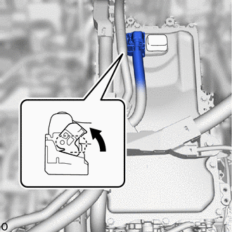
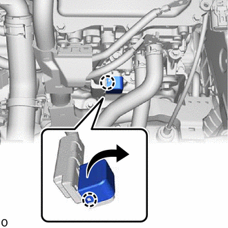
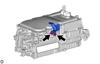
(a) Move the lock lever while pushing the lock on the connector, and disconnect the inverter with converter assembly connector. NOTICE:
|
|
|
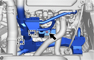
(b) Remove the bolt. |
|
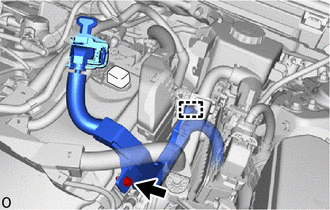
(c) Disengage the clamp and disconnect the engine room main wire.
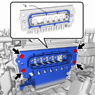
9. REMOVE CONNECTOR COVER ASSEMBLY
CAUTION:
Be sure to wear insulated gloves.
|
(a) Remove the bolt (B). |
|
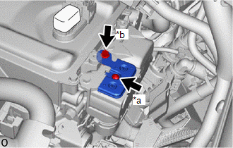
(b) Using a T25 "TORX" socket wrench, remove the bolt (A) and connector cover assembly from the inverter with converter assembly.
NOTICE:
- Do not touch the connector cover assembly waterproof seal.
- Do not allow any foreign matter or water to enter the inverter with converter assembly.
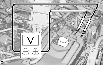
10. CHECK TERMINAL VOLTAGE
CAUTION:
Be sure to wear insulated gloves.
|
(a) Using a voltmeter, measure the voltage between the terminals of the 2 phase connectors. Standard Voltage: 0 V NOTICE: Do not allow any foreign matter or water to enter the inverter with converter assembly. HINT: Use a measuring range of DC 750 V or more on the voltmeter. |
|
11. TEMPORARILY INSTALL CONNECTOR COVER ASSEMBLY
CAUTION:
Be sure to wear insulated gloves.
|
(a) Temporarily install the connector cover assembly to the inverter with converter assembly. |
|
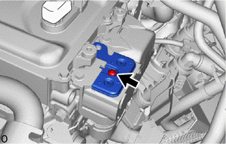
(b) Using a T25 "TORX" socket wrench, install the bolt.
Torque:
4.5 N·m {46 kgf·cm, 40 in·lbf}
NOTICE:
- Do not touch the connector cover assembly waterproof seal.
- Do not allow any foreign matter or water to enter the inverter with converter assembly.
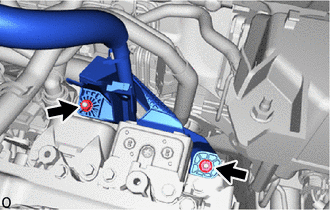
12. DISCONNECT FLOOR UNDER WIRE
CAUTION:
Be sure to wear insulated gloves.
|
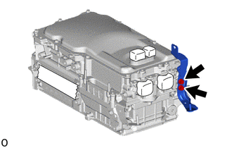
(a) Remove the 2 bolts and disconnect the HV floor under wire from the inverter with converter assembly. NOTICE:
|
|
|
(b) Remove the 2 nuts and disconnect the HV floor under wire from the inverter with converter assembly. |
|
|
(c) Remove the bolt and disconnect the HV floor under wire from the inverter with converter assembly. NOTICE:
|
|
13. DISCONNECT HV AIR CONDITIONING WIRE
CAUTION:
Be sure to wear insulated gloves.
|
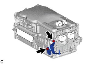
(a) Remove the 2 bolts. |
|
(b) Disengage the clamp and disconnect the HV air conditioning wire from the inverter with converter assembly.
NOTICE:
- Do not allow any foreign matter or water to enter the inverter with converter assembly.
- Do not touch the waterproof seal or terminals of the connector.
- Do not damage the terminals, connector housing or inverter with converter assembly during disconnection.
- Insulate the disconnected terminals with insulating tape.
- Cover the hole where the cable was connected with tape (non-residue type) or equivalent to prevent entry of foreign matter.
14. REMOVE WIRE HARNESS CLAMP BRACKET
|
(a) Remove the nut and wire harness clamp bracket. |
|
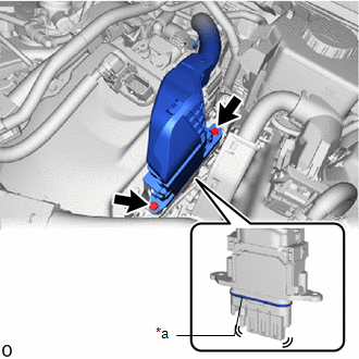
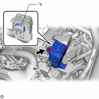
15. DISCONNECT ENGINE WIRE
CAUTION:
Be sure to wear insulated gloves.
NOTICE:
Do not allow any foreign matter or water to enter the inverter with converter assembly.
|
(a) Move the lock lever while pushing the lock on the connector, and disconnect the inverter with converter assembly connector. NOTICE:
|
|
|
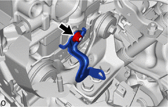
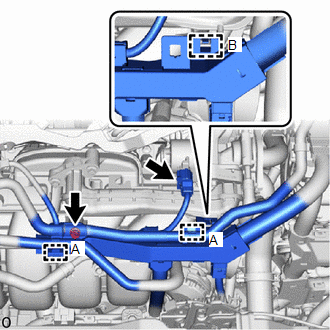
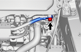
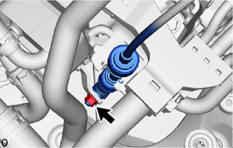
(b) Disengage the clamp (A) and disconnect the No. 1 fuel vapor feed hose. |
|
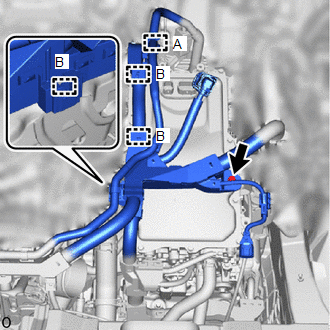
(c) Remove the bolt.
(d) Disengage the 3 clamps (B).
|
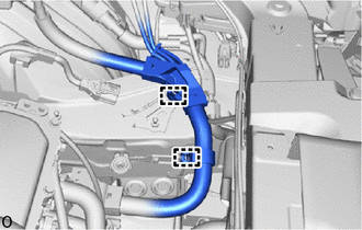
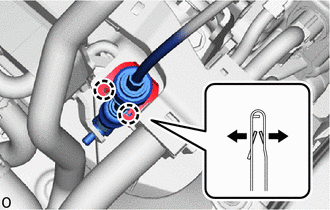
(e) Disengage the 2 clamps (A) and disconnect the No. 1 fuel vapor feed hose and No. 2 fuel vapor feed hose. |
|
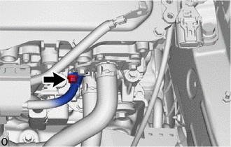
(f) Remove the bolt.
(g) Disengage the clamp (B).
(h) Disconnect the EGR valve connector.
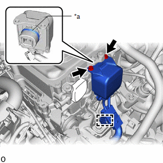
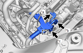
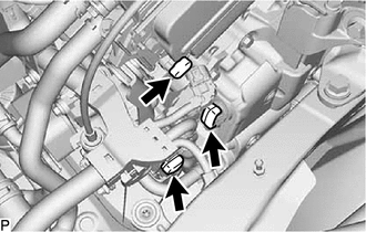
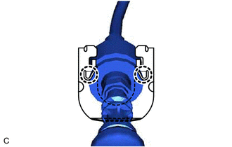
(i) Disconnect the generator temperature sensor connector, resolver (transmission fluid temperature sensor) connector and shift lever position sensor connector and disengage the clamp.
|
*a |
Generator Temperature Sensor Connector |
|
*b |
Resolver (Transmission Fluid Temperature Sensor) Connector |
|
*c |
Shift Lever Position Sensor Connector |
NOTICE:
After disconnecting the engine wire, cover the connector of the generator temperature sensor, resolver (transmission fluid temperature sensor) and shift lever position sensor with tape (non-residue type) or equivalent to prevent the entry of foreign matter or water.
|
(j) Disengage the 2 clamps. |
|
|
(k) Remove the bolt. |
|
|
(l) Remove the bolt. |
|
|
(m) Disengage the 2 claws and open the engine wire terminal cover. |
|
|
(n) Remove the nut. |
|
(o) Disengage the 2 clamps and disconnect the engine wire from the inverter with converter assembly.
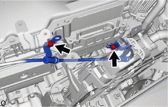
16. DISCONNECT TRANSMISSION CONTROL CABLE ASSEMBLY
|
(a) Remove the nut and disconnect the transmission control cable assembly from the control shaft lever. |
|
|
(b) Using a screwdriver, disengage the 4 claws and disconnect the transmission control cable assembly with the clip from the No. 1 transmission control cable bracket. |
|
|
(c) Using a screwdriver, disengage the 2 claws and remove the clip from the transmission control cable assembly. |
|
|
(d) Remove the 2 bolts and disconnect the transmission control cable assembly from the inverter with converter assembly. |
|
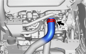
17. DISCONNECT NO. 1 INVERTER COOLING HOSE
|
(a) Slide the clip and disconnect the No. 1 inverter cooling hose from the inverter with converter assembly. NOTICE: Put pieces of cloth into the pipe and disconnected hose or cover the pipe and hose with plastic bags to prevent entry of foreign matter. |
|
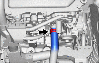
18. DISCONNECT NO. 4 INVERTER COOLING HOSE
|
(a) Slide the clip and disconnect the No. 4 inverter cooling hose from the inverter with converter assembly. NOTICE: Put pieces of cloth into the pipe and disconnected hose or cover the pipe and hose with plastic bags to prevent entry of foreign matter. |
|
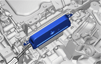
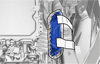
19. REMOVE INVERTER COVER
CAUTION:
Be sure to wear insulated gloves.
(a) Remove the 2 bolts and inverter cover from the inverter with converter assembly.
NOTICE:
- Make sure to pull the inverter cover straight out, as a connector is connected to the inside of the inverter cover.
- Do not touch the waterproof seal of the inverter cover.
- Do not allow any foreign matter or water to enter the inverter with converter assembly.
- When removing the inverter cover, do not pull the areas (A) as they may deform.
- Make sure that the interlock is installed to the inverter cover.
-
Do not remove or excessively tighten the screw of the inverter cover.
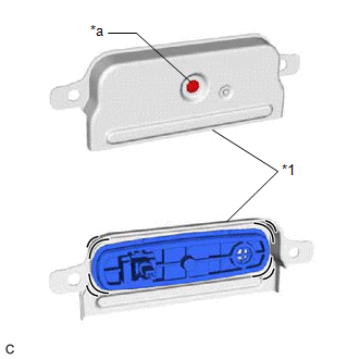
*1
Inverter Cover
*a
Do not remove or excessively tighten the screw
- Although the inverter cover may feel loose, this is not due to a malfunction.
HINT:
If necessary, use a screwdriver with its tip wrapped with protective tape as shown in the illustration to remove the inverter cover.
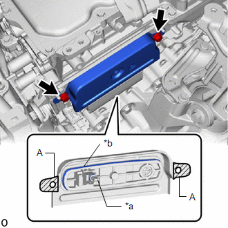
|
*a |
Interlock |
|
*b |
Waterproof Seal |
20. DISCONNECT MOTOR CABLE
CAUTION:
Be sure to wear insulated gloves.
NOTICE:
Adhere to the following removal procedure. Otherwise, the connector and the inverter with converter assembly may be damaged.
|
(a) Using an insulated tool, remove the 6 bolts. NOTICE:
|
|
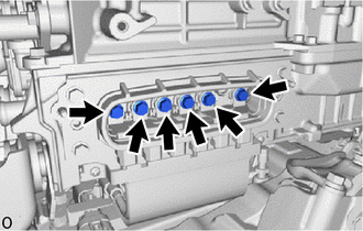
(b) Remove the 4 bolts and disconnect the motor cable from the inverter with converter assembly.
|
*a |
Waterproof Seal |
NOTICE:
- Do not allow any foreign matter or water to enter the inverter with converter assembly.
- Do not touch the waterproof seal or terminals of the motor cable.
- Do not damage the terminals, connector housing or inverter with converter assembly during disconnection.
- Insulate the disconnected terminals with insulating tape.
- After disconnecting the motor cable, wrap it with a plastic bag or equivalent to protect it.
- Cover the hole where the cable was connected with tape (non-residue type) or equivalent to prevent entry of foreign matter.
-
To prevent the wire harness from being caught, make sure to bundle the wire harness using insulating tape or equivalent.
21. REMOVE INVERTER WITH CONVERTER ASSEMBLY
CAUTION:
Be sure to wear insulated gloves.
(a) Remove the 5 bolts, 2 nuts and inverter with converter assembly.
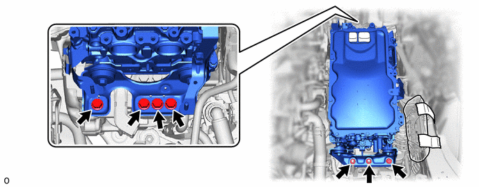
NOTICE:
- When removing the inverter with converter assembly, be careful not to damage the parts around it.
- To prevent damage, do not hold the inverter with converter assembly by the connectors, brackets or cooling pipes.
- To prevent damage due to static electricity, do not touch the terminals of the disconnected connectors.
HINT:
Even after the coolant is drained, coolant remains in the inverter due to its internal structure. Therefore, seal or cover the pipes when removing the inverter with converter assembly so that coolant does not spill out.
22. REMOVE NO. 1 INVERTER BRACKET
NOTICE:
Make sure to support the inverter with converter assembly at the positions shown in the illustration, otherwise it may be damaged.
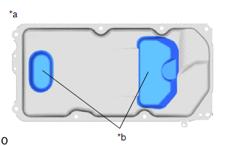
|
*a |
Bottom of Inverter with Converter Assembly |
|
*b |
Support |
|
(a) Set the inverter with converter assembly on wooden blocks. |
|
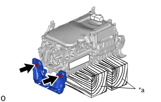
(b) Remove the 2 bolts and No. 1 inverter bracket from the inverter with converter assembly.
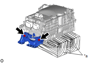
23. REMOVE NO. 2 INVERTER BRACKET
|
(a) Remove the 2 bolts and No. 2 inverter bracket from the inverter with converter assembly. |
|
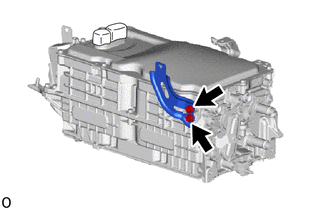
24. REMOVE WIRE HARNESS CLAMP BRACKET
|
(a) Remove the 2 bolts and wire harness clamp bracket from the inverter with converter assembly. |
|
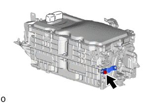
|
(b) Remove the bolt and wire harness clamp bracket from the inverter with converter assembly. |
|
|
(c) Remove the 2 bolts and wire harness clamp bracket from the inverter with converter assembly. |
|
|
(d) Remove the 2 bolts and wire harness clamp bracket from the inverter with converter assembly. |
|
|
(e) Remove the 2 bolts and wire harness clamp bracket from the inverter with converter assembly. |
|
|
|
|