- Ultrasonic sensor detection angle
- Ultrasonic sensor detection angle registration
| Last Modified: 01-30-2024 | 6.11:8.1.0 | Doc ID: RM100000002FR2B |
| Model Year Start: 2024 | Model: RAV4 | Prod Date Range: [10/2023 - ] |
| Title: PARK ASSIST / MONITORING: ULTRASONIC SENSOR (for Front): REMOVAL; 2024 MY RAV4 RAV4 HV [10/2023 - ] | ||
REMOVAL
CAUTION / NOTICE / HINT
The necessary procedures (adjustment, calibration, initialization or registration) that must be performed after parts are removed and installed, or replaced during ultrasonic sensor (for Front) removal/installation are shown below.
Necessary Procedures After Parts Removed/Installed/Replaced (for HV Model)
|
Replaced Part or Performed Procedures |
Necessary Procedures |
Effect/Inoperative Function when Necessary Procedures are not Performed |
Link |
|---|---|---|---|
|
Ultrasonic sensor |
|
|
|
|
Front bumper assembly (Including removal and installation) |
Front television camera view adjustment |
Panoramic view monitor system (for HV model) |
|
Necessary Procedures After Parts Removed/Installed/Replaced (for Gasoline Model)
|
Replaced Part or Performed Procedures |
Necessary Procedures |
Effect/Inoperative Function when Necessary Procedures are not Performed |
Link |
|---|---|---|---|
|
Ultrasonic sensor |
|
|
|
|
Front bumper assembly (Including removal and installation) |
Front television camera view adjustment |
Panoramic view monitor system (for Gasoline model) |
|
HINT:
- Use the same procedure for the RH and LH side.
- The following procedure is for the LH side.
PROCEDURE
1. REMOVE FRONT BUMPER ASSEMBLY
(a) except off road package:
Click here
![2022 - 2024 MY RAV4 RAV4 HV [12/2021 - ]; EXTERIOR PANELS / TRIM: FRONT BUMPER (except Off Road Package): REMOVAL](/t3Portal/stylegraphics/info.gif)
(b) for off road package:
Click here
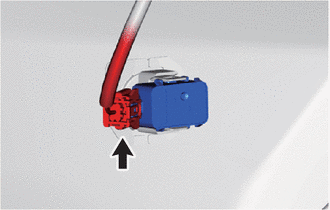
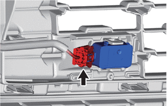
2. REMOVE FRONT ULTRASONIC SENSOR CLIP (except Off Road Package)
(a) Detach the claw and remove the front ultrasonic sensor clip.
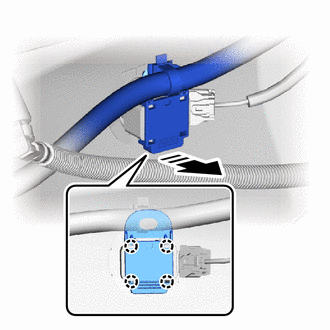

|
Remove in this Direction |
|
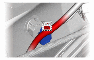
(b) Detach the wire harness clamp. |
|
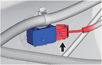
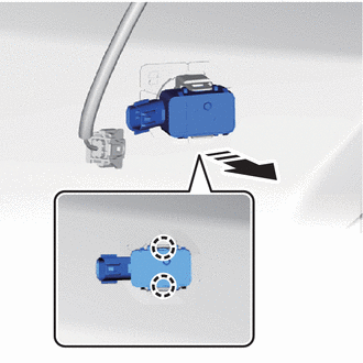
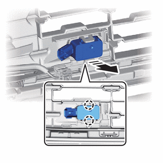
3. REMOVE FRONT CORNER ULTRASONIC SENSOR (except Off Road Package)
|
(a) Disconnect the connector. |
|
(b) Detach the claw and remove the front corner ultrasonic sensor.
NOTICE:
Before removing the sensor, make sure to mark the sensor and front bumper cover so that each sensor can be returned to its original position.
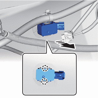
|
|
Remove in this Direction |
4. REMOVE FRONT CORNER ULTRASONIC SENSOR (for Off Road Package)
|
(a) Disconnect the connector. |
|
(b) Detach the claw and remove the front corner ultrasonic sensor.
NOTICE:
Before removing the sensor, make sure to mark the sensor and front bumper cover so that each sensor can be returned to its original position.
|
|
Remove in this Direction |
5. REMOVE FRONT CENTER ULTRASONIC SENSOR (except Off Road Package)
|
(a) Disconnect the connector. |
|
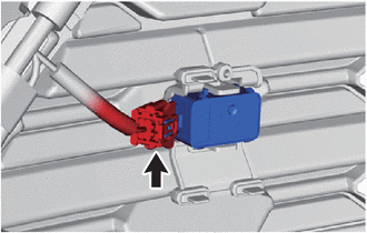
(b) Detach the claw and remove the front center ultrasonic sensor.
NOTICE:
Before removing the sensor, make sure to mark the sensor and front bumper cover so that each sensor can be returned to its original position.
|
|
Remove in this Direction |
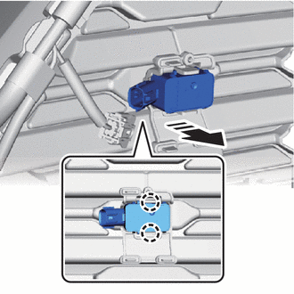
6. REMOVE FRONT CENTER ULTRASONIC SENSOR (for Off Road Package)
|
(a) Disconnect the connector. |
|
(b) Detach the claw and remove the front center ultrasonic sensor.
NOTICE:
Before removing the sensor, make sure to mark the sensor and front bumper cover so that each sensor can be returned to its original position.
|
|
Remove in this Direction |
7. REMOVE FRONT CORNER ULTRASONIC SENSOR RETAINER (except Off Road Package)
HINT:
- Perform the following procedure only when replacement of a front corner ultrasonic sensor retainer is necessary.
- When removing the front corner ultrasonic sensor retainer, if the double-sided tape is difficult to remove, heat the adhesive of the front corner ultrasonic sensor retainer and front bumper assembly using a heat light.
(a) Heat the front bumper assembly and front corner ultrasonic sensor retainer using a heat light.
CAUTION:
- Do not touch the heat light and heated parts.
- Touching the heat light may result in burns.
- Touching heated parts for a long time may result in burns.
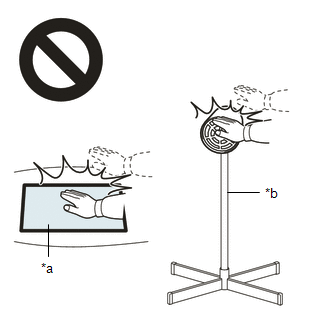
|
*a |
Heated Part |
|
*b |
Heat Light |
Standard:
|
Item |
Temperature |
|---|---|
|
Front Bumper Assembly |
40 to 60°C (104 to 140°F) |
|
Front Corner Ultrasonic Sensor Retainer |
(b) Remove the front corner ultrasonic sensor retainer.
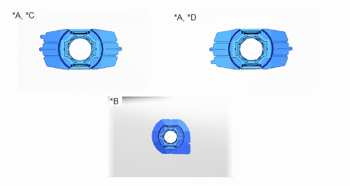
|
*A |
for TMC Made |
*B |
except TMC Made |
|
*C |
for LH Side |
*D |
for RH Side |
8. REMOVE FRONT CORNER ULTRASONIC SENSOR RETAINER (for Off Road Package)
HINT:
- Perform the following procedure only when replacement of a front corner ultrasonic sensor retainer is necessary.
- When removing the front corner ultrasonic sensor retainer, if the double-sided tape is difficult to remove, heat the adhesive of the front corner ultrasonic sensor retainer and front bumper assembly using a heat light.
(a) Heat the front bumper assembly and front corner ultrasonic sensor retainer using a heat light.
CAUTION:
- Do not touch the heat light and heated parts.
- Touching the heat light may result in burns.
- Touching heated parts for a long time may result in burns.
|
*a |
Heated Part |
|
*b |
Heat Light |
Standard:
|
Item |
Temperature |
|---|---|
|
Front Bumper Assembly |
40 to 60°C (104 to 140°F) |
|
Front Corner Ultrasonic Sensor Retainer |
(b) Remove the front corner ultrasonic sensor retainer.
|
*A |
for TMC Made |
*B |
except TMC Made |
|
*C |
for LH Side |
*D |
for RH Side |
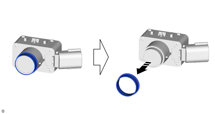
9. REMOVE ULTRASONIC SENSOR CUSHION SET
HINT:
Only perform this procedure when removing and installing the ultrasonic sensor cushion set.
(a) Remove the ultrasonic sensor cushion set as shown in the illustration.
|
|
Remove in this Direction |
- |
- |
|
|
|