| Last Modified: 01-30-2024 | 6.11:8.1.0 | Doc ID: RM100000002FQ2E |
| Model Year Start: 2024 | Model: RAV4 | Prod Date Range: [10/2023 - ] |
| Title: DOOR / HATCH: POWER BACK DOOR SYSTEM: Power Back Door cannot be Operated Using Any Switch; 2024 MY RAV4 RAV4 HV [10/2023 - ] | ||
|
Power Back Door cannot be Operated Using Any Switch |
DESCRIPTION
The power back door is controlled by the multiplex network door ECU and drives the back door motor.
If the power back door does not operate using any of the operations, a malfunction related to the power back door operation conditions or multiplex network door ECU are possible causes.
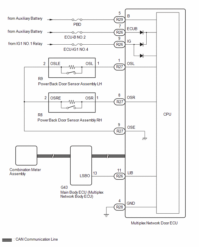
WIRING DIAGRAM
CAUTION / NOTICE / HINT
NOTICE:
-
First perform the communication function inspections in How to Proceed with Troubleshooting to confirm that there are no CAN communication malfunctions before troubleshooting this problem.
Click here
![2024 MY RAV4 RAV4 HV [10/2023 - ]; DOOR / HATCH: POWER BACK DOOR SYSTEM: HOW TO PROCEED WITH TROUBLESHOOTING](/t3Portal/stylegraphics/info.gif)
- Inspect fuses for circuits related to this system before performing the following inspection procedure.
-
If the multiplex network door ECU has been replaced, or if any of the connectors has been disconnected, initialize the power back door system.
Click here
- If the main body ECU (multiplex network body ECU) is replaced, refer to Registration.
- If the 2-step unlock function is enabled via customize settings, only the driver door unlocks when the first unlock operation is performed and the power back door does not operate as all the doors are not unlocked.
PROCEDURE
|
1. |
CHECK VEHICLE CONDITION |
(a) Operate the multi-information display and check the customization status.
|
Display |
Description |
Default |
Setting |
Relevant ECU |
|---|---|---|---|---|
|
System settings |
Function that enables or disables the power back door operation. |
On |
On or Off |
Multiplex network door ECU |
|
Result |
Proceed to |
|---|---|
|
Customization item is "On" (power back door system operation is possible) |
A |
|
Customization item is "Off" (power back door system operation is prohibited) |
B |
| B |

|
|

|
2. |
CHECK CUSTOMIZE SETTING (UNLOCK 2 OPEARTION) |
(a) Read the customize setting "Unlock 2 Opeartion" according to the display on the GTS.
for HV Model:
Click here
for Gasoline Model:
Click here
|
Result |
Proceed to |
|---|---|
|
The customize setting is "OFF" |
A |
|
The customize setting is "ON" |
B |
| B |
|
PERFORM CUSTOMIZE SETTING for HV Model: Click here
for Gasoline Model: Click here
|
|
|
3. |
CHECK CUSTOMIZE SETTING (UNLOCK KEY TWICE) |
(a) Read the customize setting "Unlock key Twice" according to the display on the GTS.
Click here
|
Result |
Proceed to |
|---|---|
|
The customize setting is "OFF" |
A |
|
The customize setting is "ON" |
B |
| B |
|
|
|
4. |
CHECK FOR DTC |
(a) Check for DTCs.
Body Electrical > Back Door > Trouble Codes
OK:
DTC is not output
| NG |
|
|
|
5. |
CHECK POWER BACK DOOR SYSTEM CONDITION |
(a) Check the power back door system condition.
|
Result |
Proceed to |
|---|---|
|
Power back door does not operate normally |
A |
|
Power back door operates normally |
B |
| B |
|
|
|
6. |
CHECK COMBINATION METER FUNCTION |
(a) Operation check
(1) Check that the shift position indicator light in the combination meter assembly operates correctly in accordance with the operation of the shift lever.
(2) Confirm that the speedometer indicates 0 km/h when the vehicle is stopped.
OK:
The meter and gauge system operates correctly.
| NG |
|
|
|
7. |
CHECK HARNESS AND CONNECTOR (MULTIPLEX NETWORK DOOR ECU - BATTERY AND BODY GROUND) |
(a) Disconnect the R26, R28 and R29 multiplex network door ECU connectors.
(b) Measure the resistance according to the value(s) in the table below.
Standard Resistance:
|
Tester Connection |
Condition |
Specified Condition |
|---|---|---|
|
R28-4 (GND) - Body ground |
Always |
Below 1 Ω |
(c) Measure the voltage according to the value(s) in the table below.
Standard Voltage:
|
Tester Connection |
Switch Condition |
Specified Condition |
|---|---|---|
|
R26-7 (ECUB) - Body ground |
Ignition switch off |
11 to 14 V |
|
R29-5 (B) - Body ground |
Ignition switch off |
11 to 14 V |
|
R26-9 (IG) - Body ground |
Ignition switch off |
Below 1 V |
|
Ignition switch ON |
11 to 14 V |
| NG |
|
REPAIR OR REPLACE HARNESS OR CONNECTOR |
|
|
8. |
READ VALUE USING GTS |
(a) Read the Data List according to the display on the GTS.
Body Electrical > Back Door > Data List
|
Tester Display |
Measurement Item |
Range |
Normal Condition |
Diagnostic Note |
|---|---|---|---|---|
|
PBD Main Switch |
Power back door ON/OFF signal |
ON or OFF |
Current customize setting displayed |
- |
|
Door Lock Signal |
Back door condition signal |
Lock or Unlock |
Lock: Back door locked Unlock: Back door unlocked |
- |
Body Electrical > Back Door > Data List
|
Tester Display |
|---|
|
PBD Main Switch |
|
Door Lock Signal |
|
Result |
Proceed to |
|---|---|
|
Either item is normal |
A |
|
"PBD Main SW" item does not switch to "ON" or "OFF" according to main switch operation |
B |
|
"Door Lock Signal" item does not switch to "Lock" or "Unlock" according to operation to lock or unlock all doors |
C |
| B |
|
| C |
|
|
|
9. |
READ VALUE USING GTS |
(a) Read the Data List according to the display on the GTS.
Body Electrical > Back Door > Data List
|
Tester Display |
Measurement Item |
Range |
Normal Condition |
Diagnostic Note |
|---|---|---|---|---|
|
PBD Touch Sensor RH |
Power back door sensor assembly RH signal |
ON, OFF or Open |
ON: Power back door sensor assembly RH pressed OFF: Power back door sensor assembly RH not pressed Open: Power back door sensor assembly RH circuit open |
- |
|
PBD Touch Sensor LH |
Power back door sensor assembly LH signal |
ON, OFF or Open |
ON: Power back door sensor assembly LH pressed OFF: Power back door sensor assembly LH not pressed Open: Power back door sensor assembly LH circuit open |
- |
Body Electrical > Back Door > Data List
|
Tester Display |
|---|
|
PBD Touch Sensor RH |
|
PBD Touch Sensor LH |
|
Result |
Proceed to |
|---|---|
|
On the GTS screen, ON or OFF is displayed accordingly |
A |
|
On the GTS screen, ON or OFF is not displayed accordingly or Open is displayed for power back door sensor assembly RH |
B |
|
On the GTS screen, ON or OFF is not displayed accordingly or Open is displayed for power back door sensor assembly LH |
C |
| A |
|
| C |
|
|
|
10. |
INSPECT POWER BACK DOOR SENSOR ASSEMBLY RH |
Click here
| NG |
|
|
|
11. |
CHECK HARNESS AND CONNECTOR (POWER BACK DOOR SENSOR ASSEMBLY RH - MULTIPLEX NETWORK DOOR ECU) |
(a) Disconnect the R8 power back door sensor assembly RH connector.
(b) Disconnect the R27 multiplex network door ECU connector.
(c) Measure the resistance according to the value(s) in the table below.
Standard Resistance:
|
Tester Connection |
Condition |
Specified Condition |
|---|---|---|
|
R8-1 (OSR) - R27-8 (OSR) |
Always |
Below 1 Ω |
|
R8-2 (OSRE) - R27-9 (OSE) |
Always |
Below 1 Ω |
|
R8-1 (OSR) or R27-8 (OSR) - Body ground |
Always |
10 kΩ or higher |
|
R8-2 (OSRE) or R27-9 (OSE) - Body ground |
Always |
10 kΩ or higher |
| OK |
|
| NG |
|
REPAIR OR REPLACE HARNESS OR CONNECTOR |
|
12. |
INSPECT POWER BACK DOOR SENSOR ASSEMBLY LH |
Click here
| NG |
|
|
|
13. |
CHECK HARNESS AND CONNECTOR (POWER BACK DOOR SENSOR ASSEMBLY LH - MULTIPLEX NETWORK DOOR ECU) |
(a) Disconnect the R9 power back door sensor assembly LH connector.
(b) Disconnect the R27 multiplex network door ECU connector.
(c) Measure the resistance according to the value(s) in the table below.
Standard Resistance:
|
Tester Connection |
Condition |
Specified Condition |
|---|---|---|
|
R9-1 (OSL) - R27-1 (OSL) |
Always |
Below 1 Ω |
|
R9-2 (OSLE) - R27-9 (OSE) |
Always |
Below 1 Ω |
|
R9-1 (OSL) or R27-1 (OSL) - Body ground |
Always |
10 kΩ or higher |
|
R9-2 (OSLE) or R27-9 (OSE) - Body ground |
Always |
10 kΩ or higher |
| OK |
|
| NG |
|
REPAIR OR REPLACE HARNESS OR CONNECTOR |
|
14. |
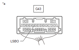
CHECK HARNESS AND CONNECTOR (MAIN BODY ECU [MULTIPLEX NETWORK BODY ECU] - MULTIPLEX NETWORK DOOR ECU) |
(a) Disconnect the G43 main body ECU (multiplex network body ECU) connector.
(b) Disconnect the R26 multiplex network door ECU connector.
(c) Measure the resistance according to the value(s) in the table below.
Standard Resistance:
|
Tester Connection |
Condition |
Specified Condition |
|---|---|---|
|
G43-13 (LSBO) - R26-11 (LIB) |
Always |
Below 1 Ω |
|
G43-13 (LSBO) or R26-11 (LIB) - Body ground |
Always |
10 kΩ or higher |
| NG |
|
REPAIR OR REPLACE HARNESS OR CONNECTOR |
|
|
15. |
CHECK MAIN BODY ECU (MULTIPLEX NETWORK BODY ECU) |
|
(a) Remove the main body ECU (multiplex network body ECU) with the connector(s) still connected. |
|
(b) Measure the voltage according to the value(s) in the table below.
Standard Voltage:
|
Tester Connection |
Condition |
Specified Condition |
|---|---|---|
|
G43-13 (LSBO) - Body ground |
Back door unlocked |
Below 1 V |
| OK |
|
| NG |
|
|
|
|