- Battery depletion
- Starter malfunction
- Starter circuit
| Last Modified: 01-30-2024 | 6.11:8.1.0 | Doc ID: RM100000002FKQN |
| Model Year Start: 2024 | Model: RAV4 | Prod Date Range: [10/2023 - ] |
| Title: A25A-FKS (ENGINE CONTROL): SFI SYSTEM: P154200; Stop and Start Cranking Time Too Long; 2024 MY RAV4 RAV4 HV [10/2023 - ] | ||
|
DTC |
P154200 |
Stop and Start Cranking Time Too Long |
DESCRIPTION
When the engine is being restarted by the stop and start system, if the engine does not start and the start time is long despite the input of the STA signal, a DTC is stored.
|
DTC No. |
Detection Item |
DTC Detection Condition |
MIL |
Note |
|---|---|---|---|---|
|
P154200 |
Stop and Start Cranking Time Too Long |
When the engine is being restarted by the stop and start system, it is detected that the engine speed is less than 400 rpm for 1.38 seconds or more (the start time is too long or the engine has not started) 2 times (2 trip detection logic). |
Comes on |
|
|
Trouble Area |
|
|---|---|
|
Starter system |
|
|
Engine |
Engine assembly |
|
Ignition system |
|
|
Fuel system |
|
|
Intake and exhaust systems |
|
|
Other control systems |
|
|
Engine |
|
|
High load from another system |
|
MONITOR DESCRIPTION
When the engine is being restarted by the stop and start system and it is detected that the engine speed is less than 400 rpm for 1.45 seconds or more 2 times (the start time is too long or the engine has not started), the ECM determines that the cranking time is too long, stores a DTC and illuminates the check engine warning light.
MONITOR STRATEGY
|
Related DTCs |
P1542: Detects no start or long cranking |
|
Required Sensors/Components (Main) |
Crankshaft position sensor |
|
Required Sensors/Components (Related) |
Camshaft position sensor |
|
Frequency of Operation |
Continuous |
|
Duration |
2 times |
|
MIL Operation |
2 driving cycles |
|
Sequence of Operation |
None |
TYPICAL ENABLING CONDITIONS
|
Monitor runs whenever the following DTCs are not stored |
None |
|
All of the following conditions are met |
- |
|
Ignition switch |
On |
|
Starter |
On |
|
Idling stop control |
On |
TYPICAL MALFUNCTION THRESHOLDS
|
Engine speed while cranking |
Less than 400 rpm |
|
Duration of cranking |
1.45 seconds or more |
CONFIRMATION DRIVING PATTERN
HINT:
-
After repair has been completed, clear the DTC and then check that the vehicle has returned to normal by performing the following All Readiness check procedure.
Click here
![2021 - 2024 MY RAV4 RAV4 HV [08/2020 - ]; A25A-FKS (ENGINE CONTROL): SFI SYSTEM: DTC CHECK / CLEAR](/t3Portal/stylegraphics/info.gif)
-
When clearing the permanent DTCs, refer to the "CLEAR PERMANENT DTC" procedure.
Click here
- Clear the DTCs (even if no DTCs are stored, perform the clear DTC procedure).
- Turn the ignition switch off and wait for at least 30 seconds.
- Start the engine and warm it up [A].
-
Drive the vehicle at 7 km/h (4.3 mph) or more.
CAUTION:
When performing the confirmation driving pattern, obey all speed limits and traffic laws.
- Depress the brake pedal and stop the vehicle.
- Keep the engine stopped by stop and start control for 1 second or more. (Keep the shift lever in D.)
- Release the brake pedal with the shift lever in D to start the engine [B].
- Repeat steps [A] through [B] above at least 2 times in one driving cycle.
- Enter the following menus: Powertrain / Engine / Trouble Codes [C].
-
Read the pending DTCs.
HINT:
- If a pending DTC is output, the system is malfunctioning.
- If a pending DTC is not output, perform the following procedure.
- Enter the following menus: Powertrain / Engine / Utility / All Readiness.
- Input the DTC: P154200.
-
Check the DTC judgment result.
HINT:
- If the judgment result is NORMAL, the system is normal.
- If the judgment result is ABNORMAL, the system has a malfunction.
- If the judgment result is INCOMPLETE, perform steps [A] through [C].
-
[A] to [C]: Normal judgment procedure.
The normal judgment procedure is used to complete DTC judgment and also used when clearing permanent DTCs.
- When clearing the permanent DTCs, do not disconnect the cable from the battery terminal or attempt to clear the DTCs during this procedure, as doing so will clear the universal trip and normal judgment histories.
CAUTION / NOTICE / HINT
HINT:
As a DTC may be stored if engine startability is poor due to insufficient fuel, it is necessary to check that the vehicle has sufficient fuel before performing this procedure.
PROCEDURE
|
1. |
CHECK ANY OTHER DTCS OUTPUT (IN ADDITION TO DTC P154200) |
(a) Perform a road test.
(b) Read the DTCs.
Powertrain > Engine > Trouble Codes
|
Result |
Proceed to |
|---|---|
|
DTC P154200 is output |
A |
|
DTC P154200 and other DTCs are output |
B |
HINT:
If any DTCs other than P154200 are output, troubleshoot those DTCs first.
| B |

|
GO TO DTC CHART |
|

|
2. |
READ VEHICLE CONTROL HISTORY FREEZE FRAME DATA AND PERFORM SYMPTOM CONFIRMATION |
(a) Confirm if any data relating to the problem symptoms exist in the Vehicle Control History.
Powertrain > Engine > Utility
|
Tester Display |
|---|
|
Vehicle Control History (RoB) |
HINT:
- It is also possible to display vehicle control history during the Health Check, if "Store All Data" is selected.
- The vehicle condition when the problem symptoms occurred can be determined by confirming the Vehicle Control History Freeze Frame Data.
- As the Vehicle Control History data may be overwritten whenever the trigger conditions are met, make sure to save the Vehicle Control History data before performing any inspections.
- Using information from the customer about when the problem symptom occurred, find the Freeze Frame Data with the appropriate Key Cycle, Total Distance Traveled, etc., to find vehicle history that may be related to the problem symptoms.
(b) Check if the problem symptoms stated by the customer are currently occurring.
HINT:
- By using snapshot to store the Data List, the Data List items can be compared to the Vehicle Control History.
-
If the problem symptoms cannot be reproduced, refer to Check for Intermittent Problems, and try to reproduce the conditions when the problem symptoms occurred as stated by the customer. If the problem symptoms still cannot be reproduced, perform the following procedure.
Click here
(c) Read the Data List or the Vehicle Control History Freeze Frame Data.
HINT:
- If the malfunction is currently occurring, compare the values of the Data List items with the vehicle control history freeze frame data.
- If the malfunction is not currently occurring, read the Vehicle Control History Freeze Frame Data.
|
Vehicle Control History |
Vehicle Control History Freeze Frame Data / Data List While Problem Symptoms Are Occurring |
Suspected Area |
Proceed to |
|---|---|---|---|
|
Engine Difficult to Start (Engine Starting Time Long) is stored (Vehicle Control History Code: X0810) |
Engine speed is 0 rpm (engine does not crank) |
Battery depletion, excessive engine friction, starter malfunction or crankshaft position sensor malfunction |
A |
|
Engine speed is between 100 and 500 rpm (engine cranks but combustion does not occur, initial combustion delays or combustion occurs late) |
Ignition system, fuel system malfunction or wire harness |
B |
|
|
Engine Difficult to Start (Engine Stall Immediately After Starting) is stored (Vehicle Control History Code: X0811) |
- |
|
B |
|
ISC F/B Learn Torque is 15 Nm or higher |
The offset correction value is insufficient due to deposits in the throttle body causing a low idle air flow rate. |
C |
|
|
Engine Difficult to Start (Immobiliser) is stored (Vehicle Control History Code: X0812) |
- |
The engine stalled due to operation of immobiliser system. Check the immobiliser system for malfunctions. |
D |
|
The malfunction is not currently occurring and there is no Vehicle Control History related to the problem symptoms stated by the customer. |
B |
||
| A |
|
| C |
|
| D |
|
|
|
3. |
CHECK INTERVIEW RESULT |
|
Result |
Proceed to |
|---|---|
|
Engine is difficult to start only when the vehicle has been left as is for a long time (1 hour or more) |
A |
|
Other than above |
B |
| B |
|
|
|
4. |
INSPECT FUEL INJECTOR ASSEMBLY |
(a) Clean the inside of the intake manifold with compressed air.
(b) After stopping the engine, measure the HC concentration inside the surge tank for 15 minutes.
|
Result |
Proceed to |
|---|---|
|
Less than 4000 ppm |
A |
|
4000 ppm or higher |
B |
HINT:
- If the concentration is 4000 ppm or higher, a fuel injector assembly may have a sealing problem.
-
Perform "Inspection After Repair" after replacing the fuel injector assembly.
Click here
| A |
|
| B |
|
REPLACE FUEL INJECTOR ASSEMBLY |
|
5. |
CHECK CRANKING |
(a) Check the engine cranking operation.
|
Result |
Proceed to |
|---|---|
|
The engine does not crank or cranks slowly |
A |
|
The engine cranks normally |
B |
| B |
|
|
|
6. |
INSPECT BATTERY |
Click here
| OK |
|
| NG |
|
CHARGE OR REPLACE BATTERY |
|
7. |
SYMPTOM CONFIRMATION |
(a) Check if the problem symptoms reported in the customer problem analysis recur.
HINT:
If the problem symptoms do not recur, attempt to reproduce the conditions when the malfunction occurred based on the result of the customer problem analysis.
|
Result |
Proceed to |
|---|---|
|
The problem symptom recurs |
A |
|
The problem symptom does not recur (occurred in the past) |
B |
| B |
|
|
|
8. |
CHECK INITIAL COMBUSTION |
(a) Check that the engine starts or there is initial combustion.
HINT:
If there is no initial combustion, perform a simple spark test by removing the bolt of the ignition coil assembly, partially lifting the ignition coil assembly, and checking for spark.
Click here
|
Result |
Proceed to |
|---|---|
|
The engine starts or there is initial combustion |
A |
|
There is no initial combustion and no spark occurs |
B |
| B |
|
|
|
9. |
READ VALUE USING GTS (ISC F/B LEARN TORQUE) |
(a) Read the value displayed on the GTS.
Powertrain > Engine > Data List
|
Tester Display |
|---|
|
ISC F/B Learn Torque |
|
Result |
Proceed to |
|---|---|
|
Less than 15 Nm |
A |
|
Other than above |
B |
| B |
|
|
|
10. |
READ VALUE USING GTS (SHORT FT B1S1 AND LONG FT B1S1) |
(a) Read the value displayed on the GTS.
Powertrain > Engine > Data List
|
Tester Display |
|---|
|
Short FT B1S1 |
|
Long FT B1S1 |
|
Data List |
Result |
Proceed to |
|---|---|---|
|
Short FT B1S1 + Long FT B1S1 |
-20% or higher, or less than 20% |
A |
|
Other than above |
B |
HINT:
- "Total FT Bank 1" is used to detect an abnormal air fuel ratio. As the value of "Total FT Bank 1" is corrected by the ECM before it is displayed in the Data List, the displayed value may not be equal to the sum of the measured "Short FT B1S1" and "Long FT B1S1".
- An abnormally lean or rich tendency can be checked by reading the following Data List items: A/F Learn Value Idle Bank 1, A/F Learn Value Low Bank 1, A/F Learn Value Mid No.1 Bank 1, A/F Learn Value Mid No.2 Bank 1, A/F Learn Value High Bank 1, A/F Learn Value Idle (Port) Bank 1, A/F Learn Value Low (Port) Bank 1, A/F Learn Value Mid No.1 (Port) Bank 1, A/F Learn Value Mid No.2 (Port) Bank 1 and A/F Learn Value High (Port) Bank 1.
-
The following may cause a lean air fuel ratio (an operating range in which the air fuel ratio learned value correction is +20% or more):
- Decrease in fuel injector assembly injection volume
- Decrease in mass air flow meter sub-assembly output (due to existence of foreign matter)
- Air leaks in intake system after mass air flow meter sub-assembly
- Decrease in fuel pressure (at fuel filter, fuel pump, fuel main valve assembly or fuel suction plate sub-assembly)
- On vehicles which the learning value for each operating range can be checked, if the value of "A/F Learn Value High (Port) Bank 1" or "A/F Learn Value High Bank 1" only is corrected to the positive side, a malfunction in the fuel system (clogging of the fuel pump or fuel filter) is suspected.
- On vehicles which the learning value for each operating range can be checked, if the value of "A/F Learn Value Idle (Port) Bank 1", "A/F Learn Value Low (Port) Bank 1", "A/F Learn Value Idle Bank 1" or "A/F Learn Value Low Bank 1" only is corrected to the positive side, an air leak after the mass air flow meter sub-assembly is suspected.
-
The following may cause a rich air fuel ratio (an operating range in which the air fuel ratio learned value correction is -20% or less):
- Increase in the fuel injector assembly injection volume
- Purge VSV system
| B |
|
|
|
11. |
PERFORM ACTIVE TEST USING GTS (D-4S (FUEL CUT)) |
(a) Start the engine.
HINT:
Reproduce the vehicle conditions when the malfunction occurred. (such as after the engine is warmed up or after a cold start).
(b) According to the display on the GTS, perform the Active Test and check for a malfunctioning cylinder.
Powertrain > Engine > Active Test
|
Active Test Display |
|---|
|
D-4S (Fuel Cut) |
|
Data List Display |
|---|
|
Engine Speed |
HINT:
- Perform fuel-cut of port injection and direct injection for each cylinder and check the change in the engine speed.
- If the engine speed of a cylinder does not change while performing the Active Test, it can be determined that the cylinder is malfunctioning.
- If the engine speed of all cylinders change while performing the Active Test, it can be determined that multiple cylinders are malfunctioning.
- A cylinder for which the Data List item "Misfire Count Cylinder #1 to #4" increases may be malfunctioning.
|
Result |
Proceed to |
|---|---|
|
One cylinder is malfunctioning |
A |
|
Multiple or all cylinders are malfunctioning, or the malfunctioning cylinder cannot be determined. |
B |
| B |
|
|
|
12. |
PERFORM ACTIVE TEST USING GTS (CHECK THE CYLINDER COMPRESSION) |
HINT:
If the vehicle does not support the Active Test "Check the Cylinder Compression", measure the compression pressure. If the compression pressure is normal, go to step 14 (PERFORM ACTIVE TEST USING GTS (D-4S (INJECTION VOLUME))).
(a) Warm up the engine.
(b) Turn the ignition switch off.
(c) Push the snapshot button to turn the snapshot function on.
Powertrain > Engine > Active Test
|
Active Test Display |
|---|
|
Check the Cylinder Compression |
|
Data List Display |
|---|
|
Engine Speed Cylinder #1 |
|
Engine Speed Cylinder #2 |
|
Engine Speed Cylinder #3 |
|
Engine Speed Cylinder #4 |
|
Average Engine Speed of All Cylinder |
HINT:
- To display the entire Data List, press the pull down menu button next to Primary. Then select Compression.
- Using the snapshot function, data can be recorded during the Active Test.
(d) While the engine is not running, press the Active button to change Check the Cylinder Compression to "Start".
HINT:
After performing the above procedure, Check the Cylinder Compression will start. Fuel injection for all cylinders is prohibited and each cylinder engine speed measurement enters standby mode.
(e) Crank the engine for about 10 seconds.
(f) Monitor the engine speed (Engine Speed Cylinder #1 to #4 and Average Engine Speed of All Cylinder) displayed on the GTS.
NOTICE:
- Do not crank the engine continuously for 20 seconds or more.
- If it is necessary to crank the engine again after Check the Cylinder Compression has been changed to "Start" and the engine has been cranked once, press Exit to return to the Active Test menu screen. Then change Check the Cylinder Compression to "Start" and crank the engine.
- Make sure the battery is fully charged before performing this Active Test.
HINT:
- At first, the GTS will display extremely high cylinder engine speed values. After approximately 10 seconds of engine cranking, the engine speed measurement of each cylinder will change to the actual engine speed.
- If the cylinder engine speed values (Engine Speed Cylinder #1 to #4) displayed in the Data List do not change from an extremely high value, return to the Active Test menu screen, change "Check the Cylinder Compression" to "Start" and crank the engine again within 1 second.
(g) Stop cranking the engine, and then change "Check the Cylinder Compression" to "Stop" after the engine stops.
NOTICE:
- If the Active Test is changed to "Stop" while the engine is being cranked, the engine will start.
- When performing the Active Test, Vehicle Control History code X0810 (Engine Difficult to Start (Engine Starting Time Long)) may be stored.
- After performing the Active Test, make sure to check and clear DTCs.
(h) Push the snapshot button to turn the snapshot function off.
(i) Select "Stored Data" on the GTS screen, select the recorded data and display the data as a graph.
HINT:
If the data is not displayed as a graph, the change of the values cannot be observed.
(j) Read the value.
HINT:
- If the value of Data List item "Engine Speed Cylinder" of a cylinder is higher than other cylinders, the cylinder may be malfunctioning.
- If the value of Data List item "Engine Speed Cylinder" is high for only one cylinder, compression loss is suspected.
|
Result |
Proceed to |
|---|---|
|
There is no variation in "Engine Speed Cylinder" (All cylinders display approximately the same value for "Engine Speed Cylinder") |
A |
|
There is variation in "Engine Speed Cylinder" (Only one cylinder displays a value for "Engine Speed Cylinder" that differs considerably) |
B |
| B |
|
|
|
13. |
PERFORM ACTIVE TEST USING GTS (D-4S (INJECTION VOLUME)) |
(a) Start the engine and warm it up until the engine coolant temperature 75°C (167°F) or higher with all the accessories switched off.
(b) Idle the engine.
(c) According to the display on the GTS, perform the Active Test and check the vehicle conditions when increasing and decreasing the fuel injection volume of port injection and direct injection.
Powertrain > Engine > Active Test
|
Active Test Display |
|---|
|
D-4S (Injection Volume) |
|
Data List Display |
|---|
|
Coolant Temperature |
HINT:
- Increase and decrease the fuel injection volume of the port injection and direct injection simultaneously and check the vehicle condition.
- Change the fuel injection volume between the minimum and maximum range of correction (e.g. -12.5% to 24.8%).
|
Result |
Proceed to |
|---|---|
|
Malfunction is still present even if the fuel injection volume is changed |
A |
|
Malfunction disappears when the fuel injection volume is changed |
B |
| B |
|
|
|
14. |
CHECK IGNITION SYSTEM |
HINT:
- Interchange the ignition coil assembly and spark plug of the malfunctioning cylinder with those of a known good cylinder and check if the malfunctioning cylinder returns to normal.
- If the spark plug of the malfunctioning cylinder is abnormally wet with fuel even after the ignition coil assembly and spark plug are replaced, a leaking fuel injector assembly is suspected.
|
Result |
Proceed to |
|---|---|
|
The malfunctioning cylinder does not return to normal |
A |
|
The malfunctioning cylinder returned to normal |
B |
| B |
|
|
|
15. |
INSPECT OTHER RELATED COMPONENTS |
(a) Check the power source circuit, wire harness and connectors.
| NEXT |
|
|
16. |
REPLACE FUEL INJECTOR ASSEMBLY |
(a) Replace the abnormal fuel injector assembly.
HINT:
- If the air fuel ratio learned value is corrected to the positive side for all operating ranges due to low fuel injector assembly injection volume, replace the fuel injector assemblies of all cylinders.
-
Perform "Inspection After Repair" after replacing the fuel injector assembly.
Click here
| NEXT |
|
|
17. |
CHECK CYLINDER COMPRESSION PRESSURE |
(a) Measure the cylinder compression pressure. If the compression pressure of a cylinder is low, inspect the engine assembly and repair or replace parts as necessary.
Click here
| NEXT |
|
|
18. |
PERFORM ACTIVE TEST USING GTS (CONTROL THE EGR STEP POSITION) |
(a) Start the engine and warm it up until the engine coolant temperature reaches 75°C (167°F) or higher.
HINT:
The A/C switch and all accessory switches should be off.
(b) Perform the Active Test and check the vehicle condition when operating the EGR valve assembly.
Powertrain > Engine > Active Test
|
Active Test Display |
|---|
|
Control the EGR Step Position |
|
Data List Display |
|---|
|
Engine Speed |
|
Coolant Temperature |
NOTICE:
- Do not leave the EGR valve open for 10 seconds or more during the Active Test.
- Be sure to return the EGR valve to step 0 when the Active Test is completed.
- Do not open the EGR valve 30 steps or more during the Active Test.
HINT:
Operate the EGR valve between step 0 and 30 when performing this step.
|
Result |
Proceed to |
|---|---|
|
Vehicle condition changes during the Active Test (Malfunction occurs when the EGR valve is open and disappears when the EGR valve is closed) |
A |
|
Vehicle condition does not change during the Active Test (Malfunction occurs whether the EGR valve is open or closed) |
B |
HINT:
During Active Test, if the idling condition does not change in response to EGR step position, then there is probably a malfunction in the EGR valve.
| B |
|
|
|
19. |
READ VALUE USING GTS (MASS AIR FLOW SENSOR) |
(a) Start the engine and warm it up until the engine coolant temperature 75°C (167°F) or higher with all the accessories switched off.
(b) According to the display on the GTS, read the Data List when the engine is running.
Powertrain > Engine > Data List
|
Tester Display |
|---|
|
Mass Air Flow Sensor |
|
Coolant Temperature |
|
Result |
Proceed to |
|---|---|
|
A |
|
Other than below |
B |
| B |
|
|
|
20. |
PERFORM ACTIVE TEST USING GTS (D-4S (INJECTION VOLUME)) |
(a) Start the engine and warm it up until the engine coolant temperature 75°C (167°F) or higher with all the accessories switched off.
(b) Warm up the air fuel ratio sensors at an engine speed of 2500 rpm for 90 seconds.
(c) Idle the engine.
(d) According to the display on the GTS, perform the Active Test and check the vehicle conditions when increasing and decreasing the fuel injection volume of port injection and direct injection.
Powertrain > Engine > Active Test
|
Active Test Display |
|---|
|
D-4S (Injection Volume) |
|
Data List Display |
|---|
|
Coolant Temperature |
|
A/F (O2) Sensor Current B1S1 |
|
A/F (O2) Sensor Current B1S2 |
NOTICE:
- The air fuel ratio sensor (sensor 1) has an output delay of a few seconds and the air fuel ratio sensor (sensor 2) has a maximum output delay of approximately 20 seconds.
- Read the output current immediately after warming up the air fuel ratio sensors to avoid an inaccurate reading due to a sensor cooling.
HINT:
- Increase and decrease the fuel injection volume of the port injection and direct injection simultaneously and check the vehicle condition.
- Change the fuel injection volume between -12 to 12%.
Standard:
|
GTS Display (Sensor) |
Injection Volume |
Current |
|---|---|---|
|
A/F (O2) Sensor Current B1S1 (Air fuel ratio (sensor 1)) |
12% |
Below -0.075 mA |
|
-12% |
More than 0.037 mA |
|
|
A/F (O2) Sensor Current B1S2 (Air fuel ratio (sensor 2)) |
12% |
Below -0.86 mA |
|
-12% |
More than 0.33 mA |
|
Result |
Proceed to |
|---|---|
|
Output current values are abnormal |
A |
|
Malfunction disappears when fuel injection volume is increased |
B |
|
Malfunction is still present when fuel injection volume is increased, even if output current values are normal |
C |
| B |
|
| C |
|
|
|
21. |
REPLACE AIR FUEL RATIO SENSORS |
(a) Replace the air fuel ratio sensor (sensor 1).
Click here
HINT:
Perform "Inspection After Repair" after replacing the air fuel ratio sensor (sensor 1).
Click here
(b) Replace the air fuel ratio sensor (sensor 2).
Click here
HINT:
Perform "Inspection After Repair" after replacing the air fuel ratio sensor (sensor 2).
Click here
| NEXT |
|
|
22. |
REPLACE FUEL INJECTOR ASSEMBLY |
(a) Replace the fuel injector assemblies of all cylinders.
HINT:
Perform "Inspection After Repair" after replacing the fuel injector assembly.
Click here
| NEXT |
|
|
23. |
PERFORM ACTIVE TEST USING GTS (ACTIVATE THE CIRCUIT RELAY (BRUSHLESS)) |
(a) When performing the Active Test, check for an operating sound from the fuel pump (for low pressure side).
Powertrain > Engine > Active Test
|
Tester Display |
|---|
|
Activate the Circuit Relay (Brushless) |
OK:
|
Activate the Circuit Relay (Brushless) |
Specified Condition |
|---|---|
|
ON |
Operating sound heard |
|
OFF |
Operating sound not heard |
| NG |
|
|
|
24. |
INSPECT FUEL PUMP (FOR LOW PRESSURE SIDE) |
(a) Attach a fuel pressure gauge and check the fuel pressure when cranking the engine and after stopping the engine.
Click here
Standard:
|
Vehicle State |
Specified Condition |
|---|---|
|
Cranking engine |
196 to 833 kPa (2.0 to 8.5 kgf/cm2, 28 to 121 psi) |
|
5 minutes after stopping engine |
98 kPa (1.0 kgf/cm2, 14 psi) or higher |
HINT:
- If there is foreign matter such as iron particles on the fuel pump, remove it.
- Make sure that there are no leaks from the fuel lines, signs of fuel leakage or fuel odors.
| NG |
|
|
|
25. |
READ VALUE USING GTS (FUEL PRESSURE (HIGH)) |
(a) Start the engine and warm it up until the engine coolant temperature is 75°C (167°F) or higher with all the accessories switched off.
(b) According to the display on the GTS, read the Data List.
Powertrain > Engine > Data List
|
Tester Display |
|---|
|
Engine Speed |
|
Coolant Temperature |
|
Fuel Pressure (High) |
|
Injection Mode |
Standard:
|
GTS Display |
Condition |
Specified Condition |
|---|---|---|
|
Fuel Pressure (High) |
|
2400 to 20000 kPag |
| NG |
|
|
|
26. |
INSPECT OTHER RELATED COMPONENTS |
HINT:
If the malfunctioning part could not be determined by performing the preceding inspections, one of the following malfunctions is suspected.
- Deposits in the intake manifold or on an intake valve
- Delay in fuel supply due to adherence of the fuel to the deposits
| NEXT |
|
|
27. |
INSPECT RELATED PARTS |
(a) Inspect the following fuel pump related parts:
- Fuel suction plate sub-assembly
- Fuel main valve assembly
- Fuel lines and connecting parts
- Fuel filter
| NEXT |
|
|
28. |
REPLACE FUEL PUMP (FOR LOW PRESSURE SIDE) |
Click here
HINT:
Perform "Inspection After Repair" after replacing the fuel pump (for low pressure side).
Click here
| NEXT |
|
|
29. |
CHECK INTAKE SYSTEM |
(a) Check for air leaks or blockage in the intake system components. If a connection problem or foreign matter is found, repair the connection or remove the foreign matter.
HINT:
- If there is foreign matter in the intake system components, remove it before proceeding to the next step.
- If there is no foreign matter in the intake system components, check for foreign matter in the mass air flow meter sub-assembly. If there is foreign matter in the mass air flow meter sub-assembly, remove it.
| NEXT |
|
|
30. |
REPLACE EGR VALVE ASSEMBLY |
Click here
HINT:
Perform "Inspection After Repair" after replacing the EGR valve assembly.
Click here
| NEXT |
|
|
31. |
REMOVE FOREIGN OBJECT (CLEAN THROTTLE BODY WITH MOTOR ASSEMBLY) |
(a) Clean off any deposits from the inside of the throttle body with motor assembly.
(b) Push open the throttle valve and wipe off any carbon from the valve and bore using a piece of cloth soaked in non-residue solvent.
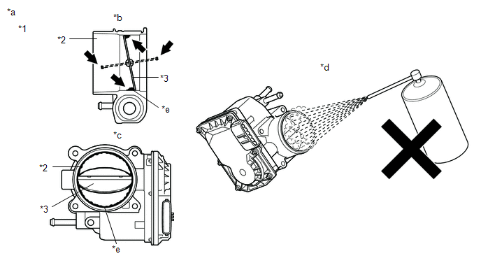
|
*1 |
Throttle Body with Motor Assembly |
*2 |
Bore |
|
*3 |
Valve |
- |
- |
|
*a |
Reference |
*b |
Throttle Body with Motor Assembly Cross-section Diagram |
|
*c |
When valve fully opened |
*d |
Do not directly apply cleaner |
|
*e |
Deposits |
- |
- |
NOTICE:
- Make sure that the cloth or your fingers do not get caught in the valve.
- Make sure that foreign matter does not enter the throttle valve.
- Do not directly apply non-residue solvent to the throttle body with motor assembly or wash the throttle body with motor assembly. Cleaning solvent may leak into the motor from the shaft and cause problems such as rust or valve movement problems.
- If there is coating material on the edge of the valve, be careful not to remove it.
HINT:
The illustrations are for reference only. Actual parts may differ.
|
|
32. |
PERFORM CONFIRMATION DRIVING PATTERN |
(a) Perform "Inspection After Repair" after cleaning the throttle body with motor assembly.
Click here
(b) Start the engine and warm it up until the engine coolant temperature reaches 75°C (167°F) or higher.
(c) Allow the engine to idle for 3 minutes or more and confirm that the engine speed is within the specified range.
HINT:
If the engine is operated without performing learning value reset and idle learning after cleaning the deposits from the throttle body with motor assembly, the idle speed may increase.
| NEXT |
|
|
33. |
CHECK IGNITION SYSTEM |
(a) Perform a spark test.
Click here
HINT:
- If there is a malfunction for a specific cylinder, exchange the ignition coil assembly and spark plug of the malfunctioning cylinder with that of another cylinder and check if the malfunction disappears.
-
If the malfunction does not disappear after the ignition coil assembly and spark plug is exchanged or spark does not occur for any cylinder, inspect the ignition circuit.
Click here
|
|
34. |
REPAIR OR REPLACE MALFUNCTIONING PARTS |
HINT:
Perform "Inspection After Repair" after repairing or replacing the malfunctioning part.
Click here
|
|
35. |
CONDUCT CONFIRMATION TEST |
(a) Check that the engine has returned to normal.
| NEXT |
|
END |
|
|
|