| Last Modified: 01-30-2024 | 6.11:8.1.0 | Doc ID: RM1000000027O8E |
| Model Year Start: 2023 | Model: RAV4 | Prod Date Range: [10/2022 - ] |
| Title: TELEMATICS: TELEMATICS SYSTEM: DCM Data Signal Circuit between Radio Receiver and DCM; 2023 - 2024 MY RAV4 RAV4 HV [10/2022 - ] | ||
|
DCM Data Signal Circuit between Radio Receiver and DCM |
DESCRIPTION
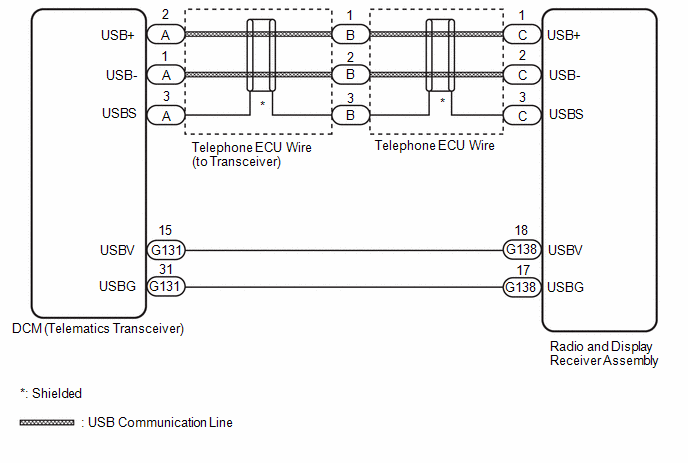
This circuit is used to send and receive signals between the DCM (telematics transceiver) and the radio and display receiver assembly.
WIRING DIAGRAM
PROCEDURE
|
1. |
INSPECT TELEPHONE ECU WIRE (TO TRANSCEIVER) |
|
(a) Disconnect the telephone ECU wire (to Transceiver) connector from the telephone ECU wire. |
|
(b) Disconnect the telephone ECU wire (to Transceiver) connector from the DCM (telematics transceiver).
(c) Measure the resistance according to the value(s) in the table below.
Standard Resistance:
|
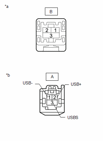
Tester Connection |
Condition |
Specified Condition |
|---|---|---|
|
B-1 - A-2 (USB+) |
Always |
Below 1 Ω |
|
B-2 - A-1 (USB-) |
Always |
Below 1 Ω |
|
B-3 - A-3 (USBS) |
Always |
Below 1 Ω |
|
B-1 or A-2 (USB+) - Body ground |
Always |
10 kΩ or higher |
|
B-2 or A-1 (USB-) - Body ground |
Always |
10 kΩ or higher |
|
B-3 or A-3 (USBS) - Body ground |
Always |
10 kΩ or higher |
| NG |

|
|

|
2. |
INSPECT TELEPHONE ECU WIRE |
|
(a) Disconnect the telephone ECU wire connector from the radio and display receiver assembly. |
|
(b) Disconnect the telephone ECU wire connector from the telephone ECU wire (to transceiver).
(c) Measure the resistance according to the value(s) in the table below.
Standard Resistance:
|
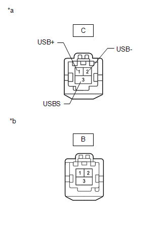
Tester Connection |
Condition |
Specified Condition |
|---|---|---|
|
C-1 (USB+) - B-1 |
Always |
Below 1 Ω |
|
C-2 (USB-) - B-2 |
Always |
Below 1 Ω |
|
C-3 (USBS) - B-3 |
Always |
Below 1 Ω |
|
C-1 (USB+) or B-1 - Body ground |
Always |
10 kΩ or higher |
|
C-2 (USB-) or B-2 - Body ground |
Always |
10 kΩ or higher |
|
C-3 (USBS) or B-3 - Body ground |
Always |
10 kΩ or higher |
| NG |
|
|
|
3. |
CHECK HARNESS AND CONNECTOR (DCM [TELEMATICS TRANSCEIVER] - RADIO AND DISPLAY RECEIVER ASSEMBLY) |
(a) Disconnect the G138 radio and display receiver assembly.
(b) Disconnect the G131 DCM (telematics transceiver) connector.
(c) Measure the resistance according to the value(s) in the table below.
Standard Resistance:
|
Tester Connection |
Condition |
Specified Condition |
|---|---|---|
|
G138-18 (USBV) - G131-15 (USBV) |
Always |
Below 1 Ω |
|
G138-17 (USBG) - G131-31 (USBG) |
Always |
Below 1 Ω |
|
G138-18 (USBV) - Body ground |
Always |
10 kΩ or higher |
|
G138-17 (USBG) - Body ground |
Always |
10 kΩ or higher |
| OK |
|
PROCEED TO NEXT SUSPECTED AREA SHOWN IN PROBLEM SYMPTOMS TABLE |
| NG |
|
REPAIR OR REPLACE HARNESS OR CONNECTOR |
|
|
|